Positioning device of dedusting and cleaning dolly and positioning method thereof

A technology for cleaning trolleys and positioning devices, which is applied in separation methods, chemical instruments and methods, and separation of dispersed particles. It can solve problems such as high labor intensity, dust pollution, and frequent movement of trolleys, so as to reduce labor intensity and improve the use effect. and longevity effects

Inactive Publication Date: 2013-11-13
GANZHOU JIANGWU NEW TYPE ALLOY MATERIAL
View PDF3 Cites 3 Cited by
  • Summary
  • Abstract
  • Description
  • Claims
  • Application Information

AI Technical Summary

Problems solved by technology

[0003] Because the cleaning trolley is inside the dust removal system, the trolley moves frequently, is polluted by dust, and labor-intensive. It is not suitable to manually manipulate the cleaning trolley for cleaning and dust removal.

Method used


Image

  • Positioning device of dedusting and cleaning dolly and positioning method thereof

Examples


Embodiment 1

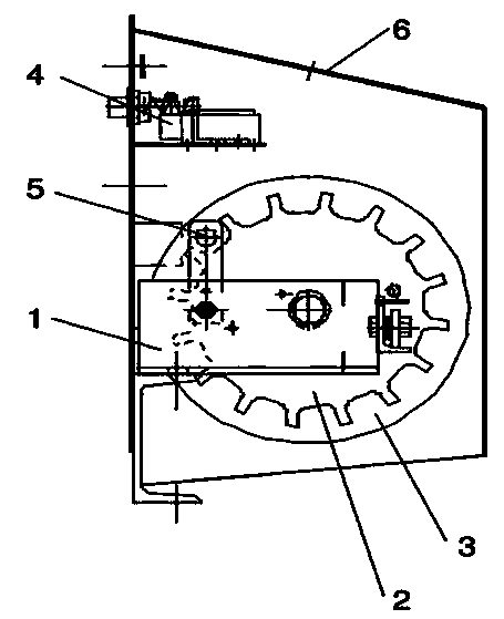
[0011] Example 1 Such as figure 1 Shown: a positioning device for a dust removal and cleaning trolley, including a cleaning trolley pulled by a traction wire rope. The wheels of the cleaning trolley walk along the track laid in front of the suspended dust bag; the bracket 1 connected to the casing 6 is installed on the cleaning trolley On the top, the guide disc 2 with indexing teeth and the sprocket 3 are installed concentrically on the rotating shaft of the bracket 1, and when the cleaning trolley moves forward, the guide disc 2 is driven to rotate by the sprocket 3; the guide disc 2 is indexed An inductive switch 5 is installed on the side of the tooth, and the inductive switch 5 is connected with the programmable controller PLC, and a terminal limit switch 4 is installed at the limit position of the edge.

Embodiment 2

[0012] Example 2 Such as figure 1 Shown: Adopt the positioning method of a positioning device for dust removal and cleaning trolley described in Example 1: the cleaning trolley is pulled by the traction wire rope and walks along the track laid in front of the suspended dust removal bag, and the cleaning trolley is driven to move forward. The guide disc 2 of the tooth rotates; whenever an indexing tooth passes and triggers the induction switch 5 installed on the side of the indexing tooth of the guide disc 2, the induction switch 5 counts once, and the programmable switch connected with the induction switch 5 Write a counting program in the PLC program of the controller, and the cleaning trolley will accurately stop in front of the dust bag that needs to be cleaned and purged, and the exact position of the cleaning trolley can be known through the cumulative calculation of the counting program; when the cleaning trolley moves to the edge limit position, trigger the terminal l...


PUM


Abstract

The invention relates to a positioning device of a dedusting and cleaning dolly. A stent, which is connected to a hood, is arranged on a dedusting and cleaning dolly. A guiding disc with an index gear and a chain wheel are integrally arranged on the rotating shaft of the stent and are in the same axis. The guiding disc is driven by the chain wheel when the cleaning cart moves forward. A sensing switch is arranged in the side surface of the index gear of the guiding disc, the sensing switch is connected to the PLC, and a terminal limit switch is arranged on a margin extreme position. The positioning method of the positioning device is as follows: when the index gear goes through and triggers the sensing switch, which is arranged on the side surface of the index gear of the guiding disc, the sensing switch counts for one time and writes a counting program in the program of the PLC, which is connected to the sensing switch, and thus the precise position of the cleaning cart can be known through accumulation operation of the counting program. The cleaning cart can be positioned automatically, direct operation of the cleaning cart in the dust-polluted environment by the operators is avoided, and the work strength of using and maintenance of the cleaning cart of the operators is reduced.

Description

technical field [0001] The invention relates to the technical field of dust removal, in particular to a positioning device for a dust removal cleaning trolley and a positioning method thereof. Background technique [0002] The core component of the bag dust removal is the bag, but the bag needs to absorb dust during use, which will lead to a decrease in the air permeability of the dust removal over time. At this time, the bag needs to be cleaned and purged. Yes, the bag can Guarantee its dust adsorption capacity for a long time, so as to ensure its good dust removal effect. The function of the cleaning trolley is to purge the cloth bag to ensure the dust removal performance of the cloth bag. The wheels of the cleaning trolley walk along the track laid in front of the suspended cloth bag and are pulled by the traction wire rope, but [0003] Because the cleaning trolley is inside the dust removal system, the trolley moves frequently, is polluted by dust, and is labor-intensi...

Claims


Application Information

Patent Timeline
Patent Type & Authority Applications(China)
IPC IPC(8): B01D46/04
Inventor 刘侠尹家军饶勇平赖后林
Owner GANZHOU JIANGWU NEW TYPE ALLOY MATERIAL
Why Eureka
Try Eureka