Cooling fan

A heat dissipation fan and fan wheel technology, applied to components of pumping devices for elastic fluids, non-variable pumps, machines/engines, etc.

Inactive Publication Date: 2013-11-13
ADDA
View PDF7 Cites 5 Cited by
  • Summary
  • Abstract
  • Description
  • Claims
  • Application Information

AI Technical Summary

Problems solved by technology

[0004] The purpose of the present invention is to overcome the defects of the existing cooling fan and provide a new type of coolin

Method used


Image

  • Cooling fan
  • Cooling fan
  • Cooling fan

Examples


Embodiment Construction

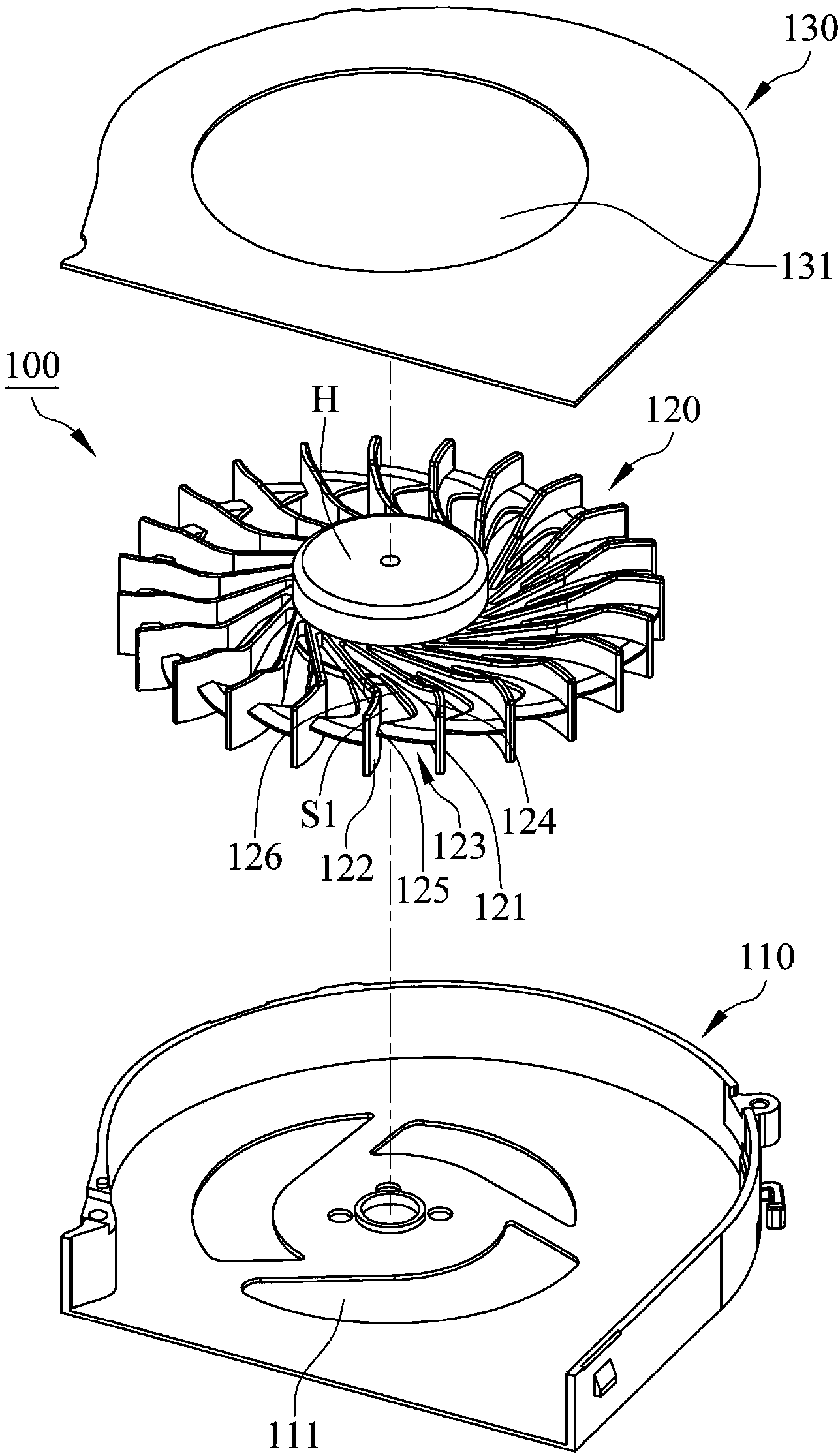
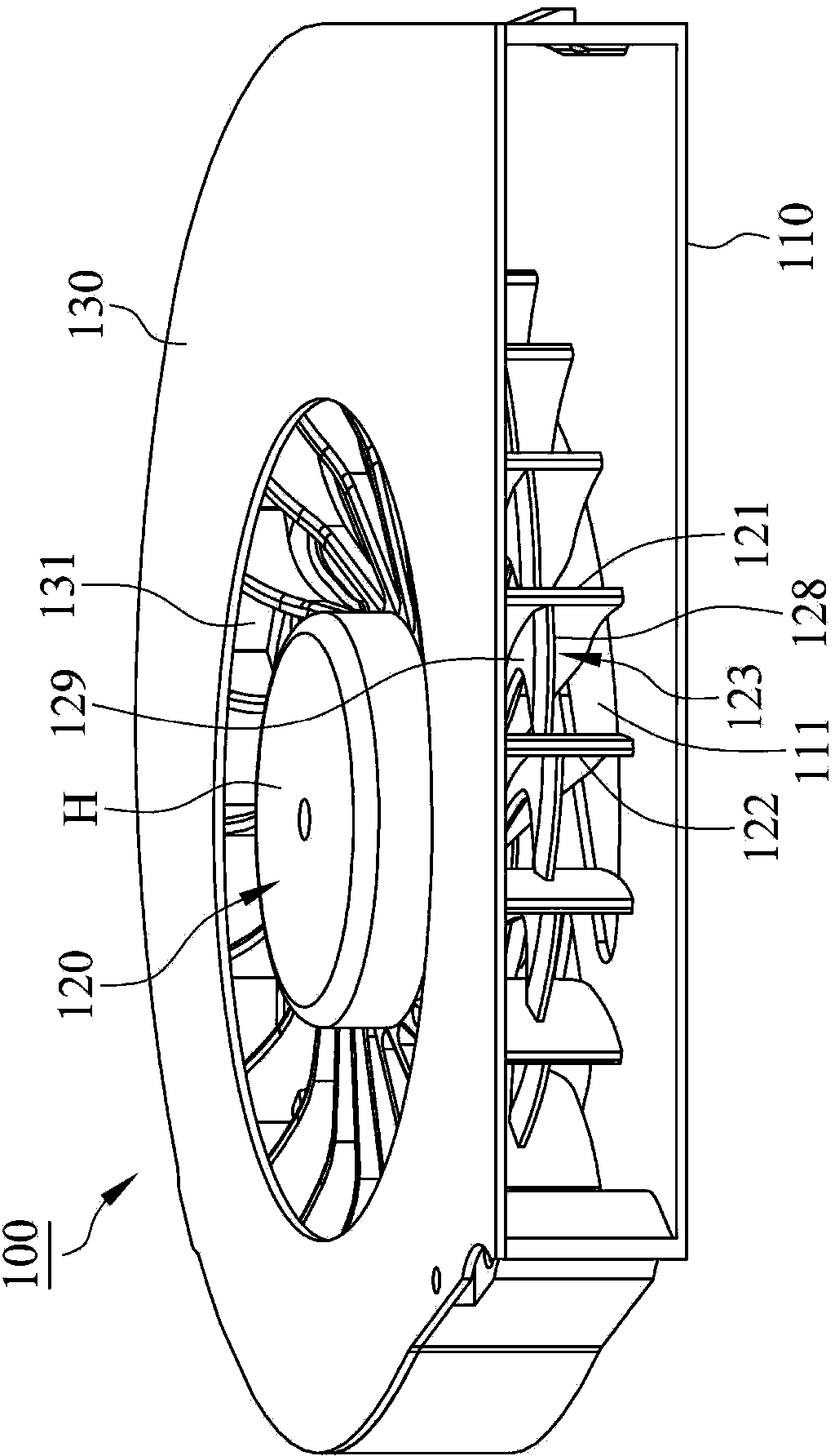
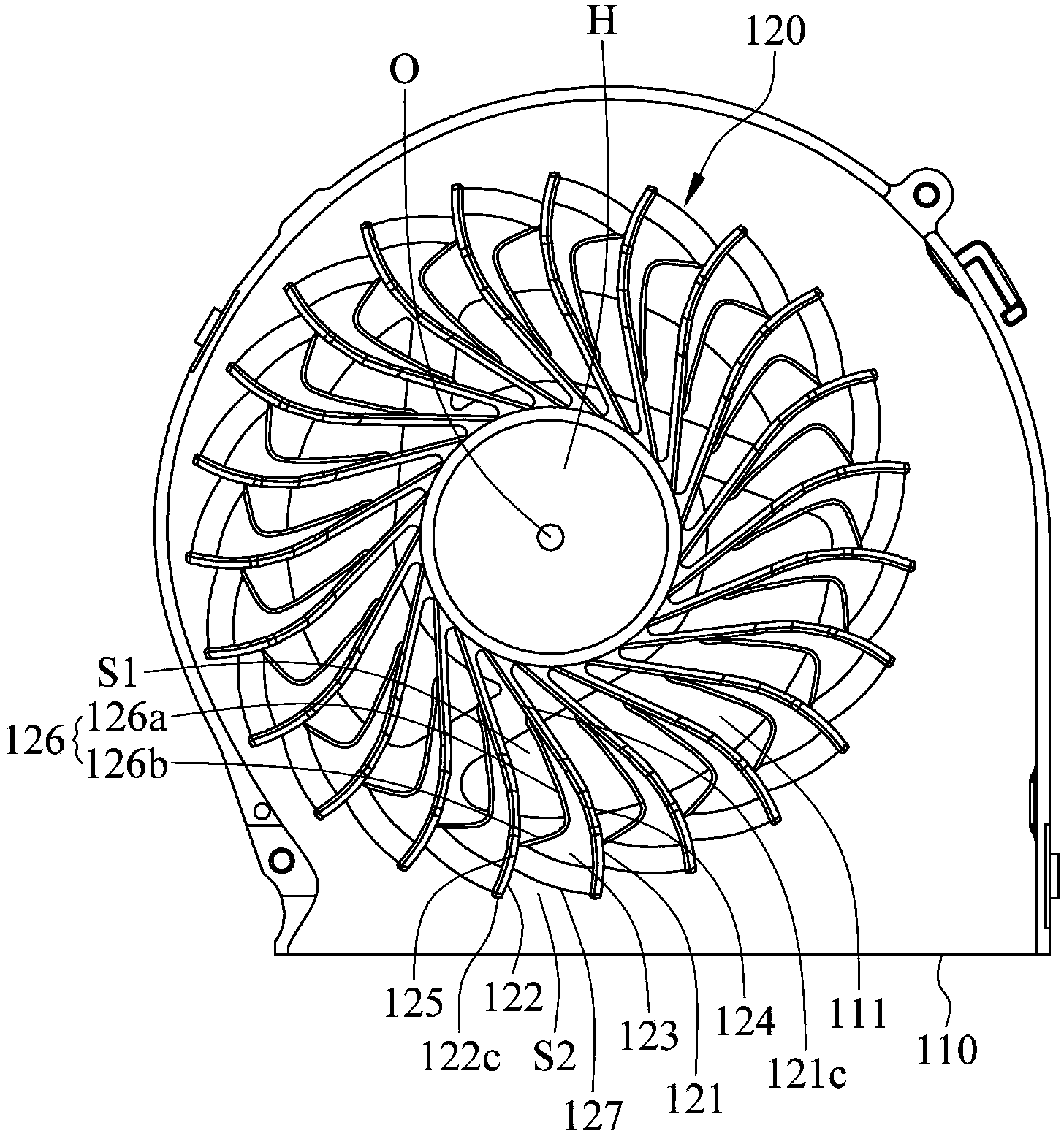
[0062] In order to further explain the technical means and effects of the present invention to achieve the intended purpose of the invention, the specific implementation, structure, characteristics and effects of the cooling fan proposed according to the present invention will be described below in conjunction with the accompanying drawings and preferred embodiments. Details are as follows.

[0063] The aforementioned and other technical contents, features and effects of the present invention will be clearly presented in the following detailed description of preferred embodiments with reference to the drawings. Through the description of specific embodiments, a more in-depth and specific understanding of the technical means and effects adopted by the present invention to achieve the intended purpose can be obtained. However, the accompanying drawings are only for reference and description, and are not used to explain the present invention. be restricted.

[0064] see figure...


PUM


Abstract

The invention relates to a cooling fan, which comprises a pedestal and a fan roller which is arranged on the pedestal. The fan roller consists of a plurality of first blades, a plurality of second blades and a plurality of connecting ribs, each first blade and each second blade are mutually arranged at intervals, each connecting rib is provided with a first edge, a second edge and a third edge, wherein the first edge is connected with a first blade, the second edge is connected with a second blade, the third edge is connected with the first edge and the second edge, a first wind inlet is formed between each third edge and each second blade, each first edge is provided with a first length, each second edge is provided with a second length, and the first length is larger than the second length.

Description

technical field [0001] The invention relates to a fan, in particular to a cooling fan. Background technique [0002] The use of fans is closely related and inseparable to people. For a known cooling fan, please refer to Figure 12 As shown, the cooling fan 200 has a base 210, a fan wheel 220 arranged on the base 210 and a cover plate 230 covering the fan wheel 220, wherein the fan wheel 220 has a hub 221 and multiple A fan blade 222, when the fan wheel 220 is driven and starts to rotate, the air is slapped by the rotating fan blades 222 and blows out sideways to achieve the effect of heat dissipation, but the fan wheel 220 does not have a suitable The air guide design, therefore, when the air enters the fan blades 222 , a turbulence phenomenon will be generated between the fan blades 222 to reduce the air output, and noise will be generated due to the turbulence phenomenon. [0003] In view of the defects of the above-mentioned existing cooling fans, the inventor actively r...

Claims


Application Information

Patent Timeline
IPC IPC(8): F04D29/28F04D29/42
Inventor 苏彦民黄高川赖启平郭俊贤
Owner ADDA
Why Eureka
Try Eureka