Self-propelled trolley driven by gravitational potential energy and capable of travelling around splay route

A technology of gravitational potential energy and self-propelled cars, which is applied to toy cars, toys, entertainment, etc., can solve the problems of affecting the traveling distance of the car, easily ignoring external conditions, and difficulty in changing the transmission ratio, so as to solve the problem of car driving transmission ratio selection, walking The trajectory is accurate and the effect of simplifying the amount of complicated calculations

Inactive Publication Date: 2013-11-20
XIAN UNIV OF SCI & TECH
View PDF8 Cites 8 Cited by
  • Summary
  • Abstract
  • Description
  • Claims
  • Application Information

AI Technical Summary

Problems solved by technology

At present, the main problems of the self-propelled trolleys known in the art are: the transmission mechanism of the trolley mainly adopts the cam-link scheme, which affects the traveling distance of the trolley due to excessive energy consumption and low efficiency; It is difficult to change the transmission ratio, which makes it difficult to change the trolley during the trajectory adjustment process. The trajectory change parameters cannot provide direct modification guidance for the fine-tuning parameters of the trolley, etc.
In addition, at present, the transmission ratio of the transmission mechanism of the carbon-free trolley is mainly estimated by experience and the guidance mechanism, which cannot be obtained more accurately, and because most of its theoretical calculations are calculated under ideal conditions, it is easy to ignore the influence of external conditions on it

Method used


Image

  • Self-propelled trolley driven by gravitational potential energy and capable of travelling around splay route
  • Self-propelled trolley driven by gravitational potential energy and capable of travelling around splay route
  • Self-propelled trolley driven by gravitational potential energy and capable of travelling around splay route

Examples


Embodiment Construction

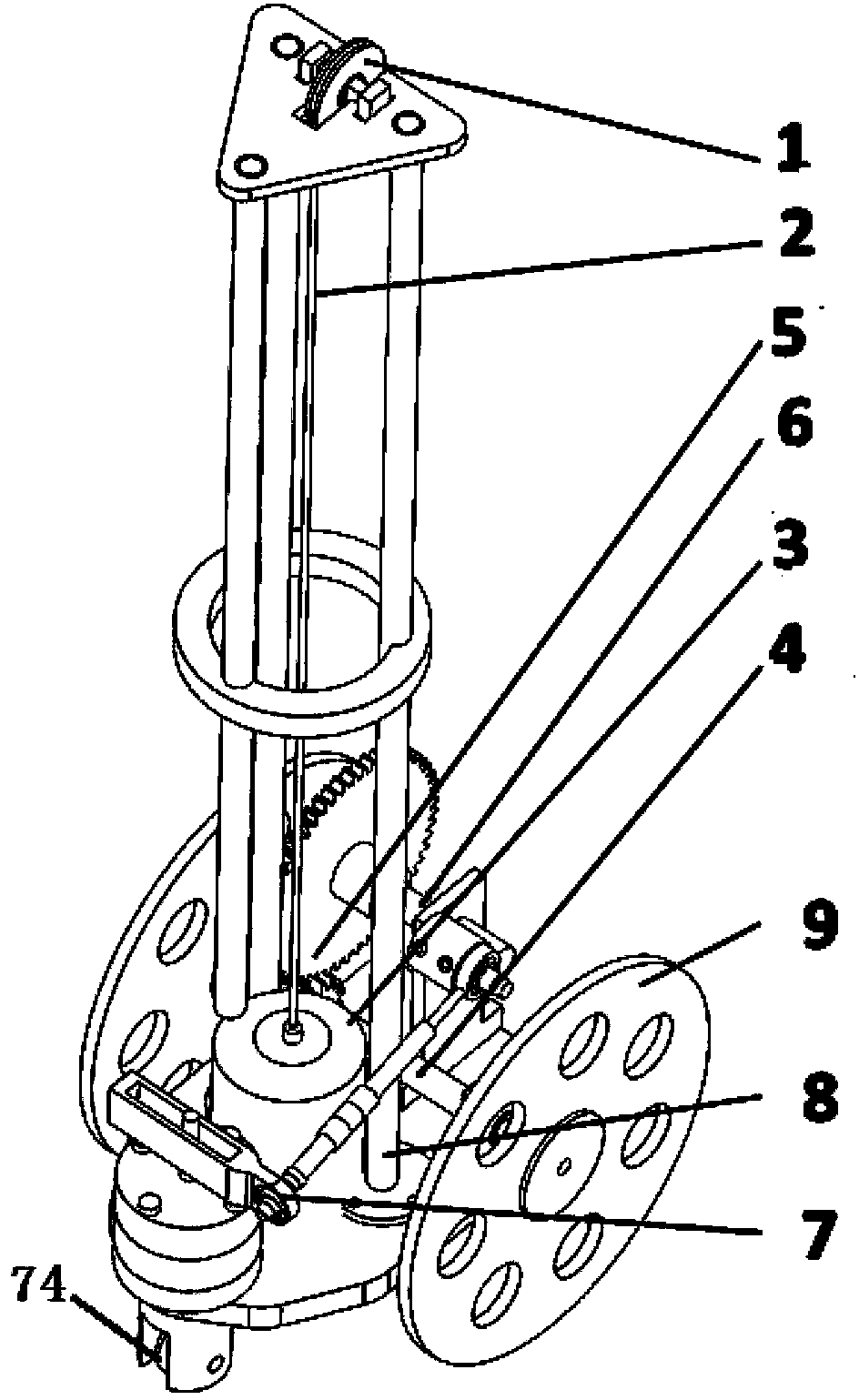
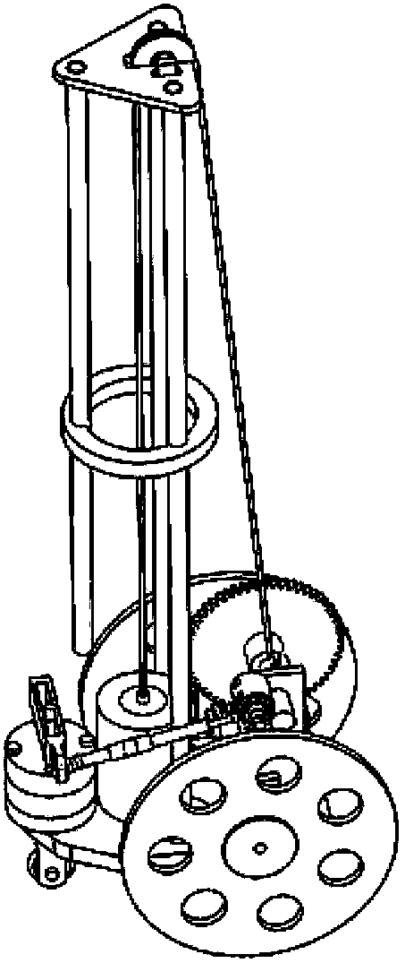
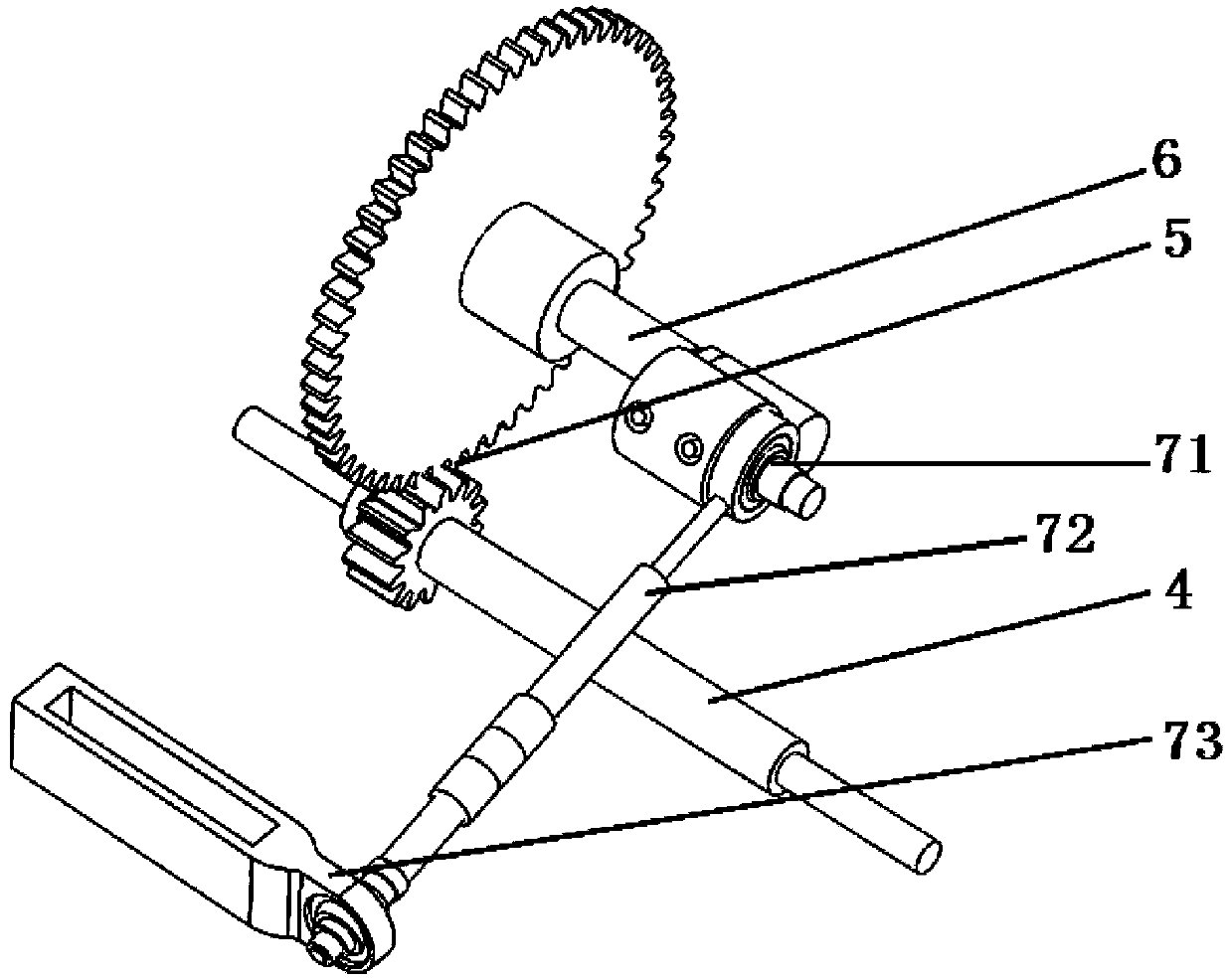
[0032] see figure 1 with figure 2 , the self-propelled trolley that can walk around the figure-of-eight route driven by gravitational potential energy of the present invention includes a chassis with rear traveling wheels 9 and a driving part and a steering mechanism 7 installed on the chassis. The driving part wherein is made up of weight support 8, weight 3, drive shaft 6 with winding shaft, winding wheel 1, connecting rope 2, transmission gear set 5 and driving shaft 4. One end of the connecting rope 2 is connected to the weight 3, and the other end is wound around the winding wheel 1 arranged at the top of the weight bracket 8 and wound on the winding shaft 6 of the drive shaft located at the bottom of the pole support 8, and the drive shaft 6 Set coaxially with the rotating shaft of a gear in the transmission gear set 5, the center of the other gear in the transmission gear set 5 is fixedly connected with the center of the rear road wheel 9 through the driving shaft 4. ...


PUM


Abstract

The invention relates to a self-propelled trolley driven by gravitational potential energy and capable of travelling around a splay route. The self-propelled trolley comprises a chassis with rear travelling wheels, a driving portion and a steering mechanism, wherein the driving portion and the steering mechanism are mounted on the chassis, the driving portion consists of a weight support, a weight, a drive shaft, a reel, a connecting cord, a transmission gear set and a driving shaft, and the steering mechanism consists of a set of spatial four-bar guide mechanism and a front guide wheel mounted below a tail oscillating bar of the spatial four-bar guide mechanism. In the actual travelling process, the front guide wheel of the trolley is controlled to rotate according to a set direction by adjusting the spatial four-bar guide mechanism so as to drive the trolley to be capable of travelling around the splay route, and various parameters of a crank bar are changed to further enable travelling distance and travelling track of the trolley to be changed. The self-propelled trolley has the advantages of simple and reasonable structure, convenience in operation and control, high efficiency, accurate travelling track, good stability and the like.

Description

technical field [0001] The invention belongs to the technical field of walking tools for experiments or toys, and relates to a self-propelled trolley that converts gravitational potential energy into kinetic energy to drive the trolley to walk around a figure-eight route. Background technique [0002] The self-propelled car is also called a carbon-free car. It is a kind of energy that does not need to consume fuel and battery storage. It only relies on the mechanical potential energy generated during the falling of the heavy hammer to generate power to drive the car forward. topic. Its basic structure can be found in figure 1 . In the figure, the connecting rope 2 hanging on the weight 3 applies gravity to the driving shaft 6 through the reel 1, and the displacement generated by the falling of the weight 3 is converted into the driving shaft by using the connecting rope through the guide wheel on the shaft The driving shaft 6 and the driving shaft 4 drive the rear wheel (...

Claims


Application Information

Patent Timeline
IPC IPC(8): A63H17/00A63H17/26
Inventor 黄海郝昱宇常智豪桑迪尚长春田俊峰王嵩
Owner XIAN UNIV OF SCI & TECH
Why Eureka
Try Eureka