Automatic power supply equipment and power supply method for closed track running inspection trolley

A technology for automatic power supply and rail operation, which is applied in the directions of running rail devices, vehicle parts, transportation and packaging, etc. It can solve the problems of complex mechanical structure, affecting the operation of mobile trolleys, and inability to operate, so as to achieve simple and reliable mechanical structure and avoid duplication. The effect of route operation, simple and reliable structure

Active Publication Date: 2015-09-09
成都慧拓自动控制技术有限公司
View PDF5 Cites 0 Cited by
  • Summary
  • Abstract
  • Description
  • Claims
  • Application Information

AI Technical Summary

Problems solved by technology

The car is automatically contacted and charged. The whole system is simple in structure and only needs to be controlled by a simple power switch. However, this method cannot meet the requirements for the mobile car to operate on a closed route. At the same time, when the mobile car is insufficient, it can only return to charge from one direction, wasting a lot of time.
[0007] In the above-mentioned traditional technologies, the common mechanical structure can realize basic moving functions, but the power supply mechanism needs to automatically extend out to contact the moving trolley; the moving trolley runs along a closed route, but the mechanical structure is relatively complicated, and it needs to provide power separately to make the power supply module run. Arrangement points affect the operation of the mobile trolley; although the mechanical structure is simple, the mobile trolley can only return in one direction and cannot run along a closed route, which wastes a lot of time

Method used


Image

  • Automatic power supply equipment and power supply method for closed track running inspection trolley
  • Automatic power supply equipment and power supply method for closed track running inspection trolley
  • Automatic power supply equipment and power supply method for closed track running inspection trolley

Examples


Embodiment Construction

[0026] The present invention will be further described below in conjunction with accompanying drawing:

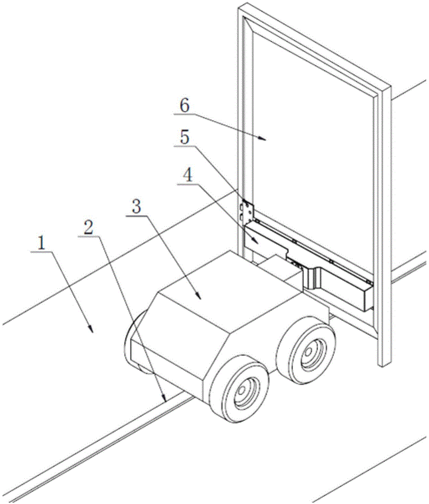
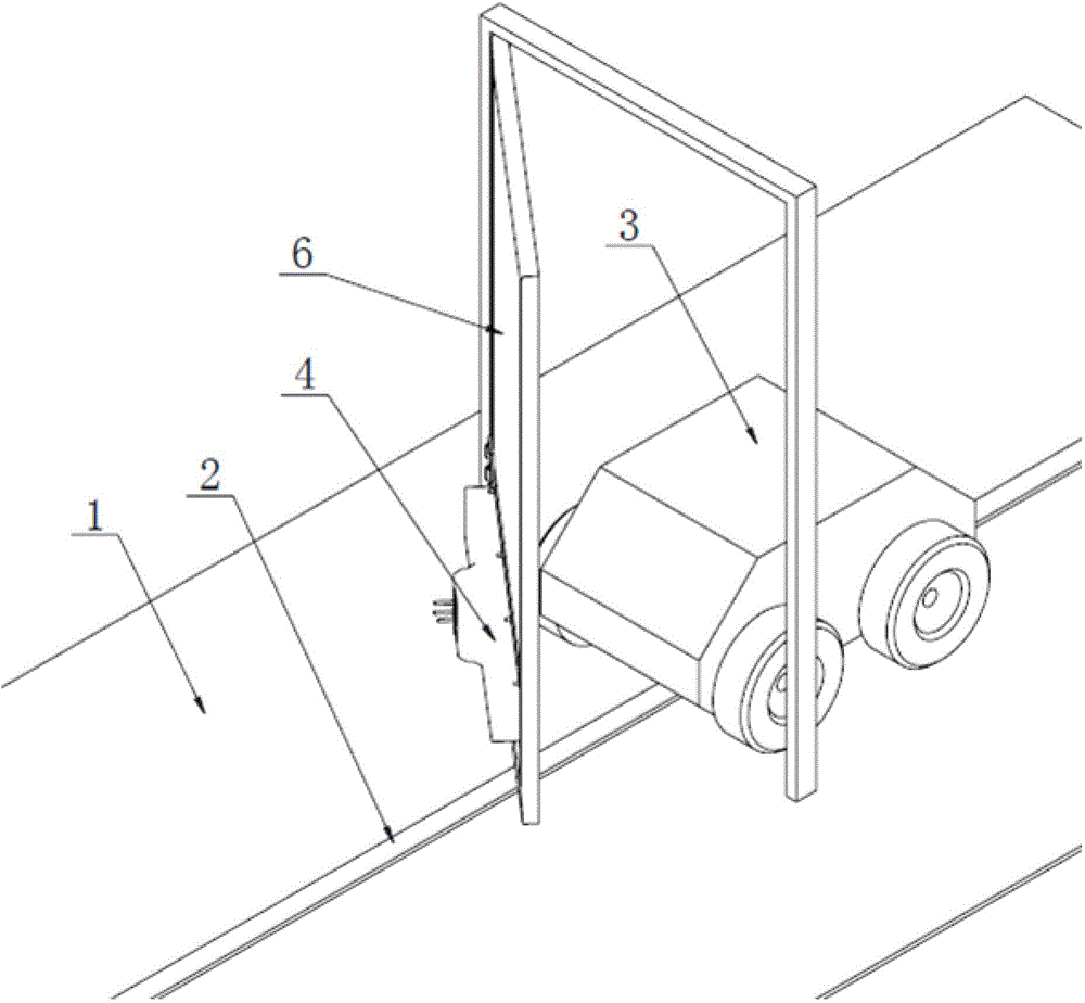
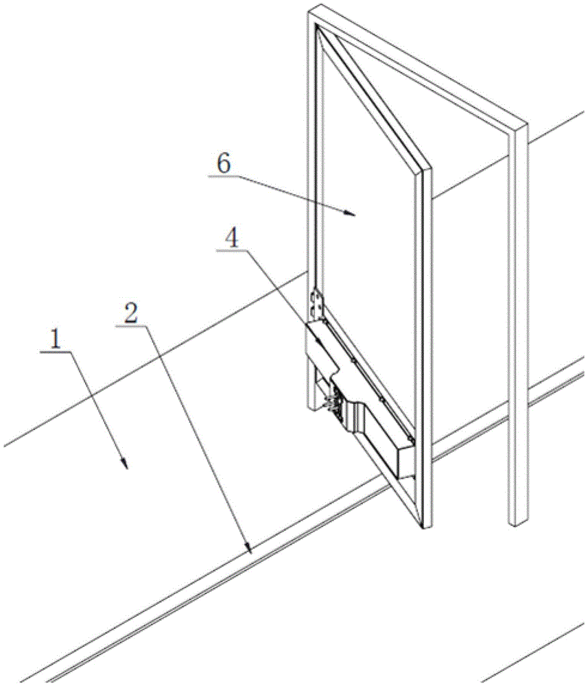
[0027] Such as Figure 1 to Figure 6 As shown: the present invention is an automatic power supply device for a patrol trolley running on a closed track. The navigation rail 2 is laid on the ground 1, and the patrol trolley 3 is placed on the navigation rail 2 and can move along the navigation rail 2. The automatic power supply equipment includes One-way door 6 and automatic door closing device 5, one-way door 6 is arranged on the top of navigation rail 2, the door-opening direction of setting one-way door 6 is the direction from back to front, and the rear end of mobile trolley 3 is equipped with charging plug or Charging socket (4 in the figure represents charging plug or charging socket), and corresponding charging socket or charging plug is installed on the rear side surface of one-way door 6, and automatic door closing device 5 is installed between the facade and door f...


PUM


Abstract

The invention discloses automatic power supply equipment and method for closed-track operating inspection trolleys. An inspection trolley is disposed on a navigation track and can move along the same. The automatic power supply equipment comprises a one-way door and an automatic door closer. The one-way door is arranged above the navigation track. The one-way door is opened from back to front. The rear end of a mobile trolley is provided with a charge plug or charge socket. A corresponding charge socket or charge plug is mounted on the rear surface of the one-way door. The automatic door closer is mounted between the surface and frame of the one-way door. The automatic power supply equipment and method have the advantages that vehicle operation postures can be automatically adjusted according to the position of an electric mechanism, with no influence upon the operating direction of the mobile trolley; charging is started after automatic contact, and elastic contact guarantees reliable charging; the mechanical structure is simple and reliable, with no need for automatic operation and independent power sources; the mobile trolley can bidirectionally return to be charged, and accordingly repeated operation on a line is avoided and time is saved.

Description

technical field [0001] The invention relates to a power supply system, in particular to an automatic power supply device and a power supply method for a trolley running on a closed track. Background technique [0002] At present, mobile cars use high-quality on-board rechargeable battery packs to power the mechanical body, but generally they can only last for a few hours. Once the power is exhausted, manual intervention must be used to charge the robot. Using manual intervention to charge the robot, the car is in a discontinuous work. It will also consume human resources. At the same time, as mobile cars are more and more widely used, people have higher and higher requirements for mobile robots to be on duty for a long time, extend working hours and improve work efficiency. Therefore, autonomous charging of mobile cars has become an urgent problem to be solved. [0003] At the same time, with the increasing use of mobile cars, there are various requirements for the working...

Claims


Application Information

Patent Timeline
Patent Type & Authority Patents(China)
IPC IPC(8): B60M7/00
Inventor 宋晖
Owner 成都慧拓自动控制技术有限公司
Why Eureka
Try Eureka