Wind-driven accelerating wing

A technology of accelerating wings and wind energy, which is applied to wind turbines, wind turbine combinations, wind turbines at right angles to the wind direction, etc., can solve the problems of large structure and low wind utilization efficiency, and achieve safe and reliable operation, high economic added value, Beautiful structure and elegant effect

Inactive Publication Date: 2013-11-20
钟明华
View PDF6 Cites 4 Cited by
  • Summary
  • Abstract
  • Description
  • Claims
  • Application Information

AI Technical Summary

Problems solved by technology

[0004] The purpose of the present invention is to overcome the defects of low wind power utilization efficiency and bulky structure of the known wind energy power wing, and provide the public with a unique wind energy power acceleration device

Method used


Image

  • Wind-driven accelerating wing
  • Wind-driven accelerating wing
  • Wind-driven accelerating wing

Examples


Embodiment Construction

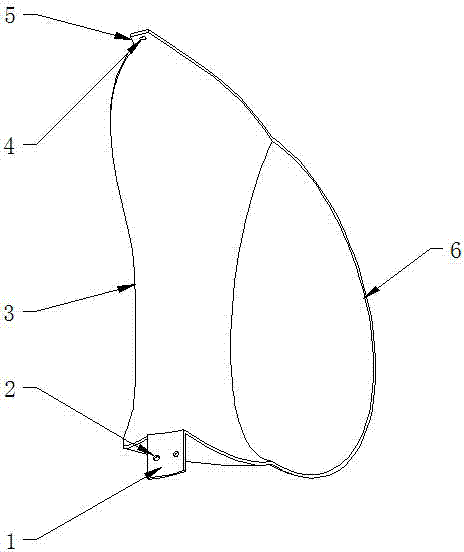
[0031] As a technical solution for product manufacturing, the present invention can make the solution concretely implemented through the organic combination of corresponding components. The product organization structure of an embodiment of the present invention is as follows: figure 1 shown.

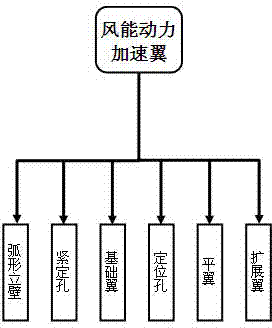
[0032] figure 1 Among them, the product is only composed of six components: arc-shaped vertical wall, fastening hole, base wing, positioning hole, flat wing and expansion wing.

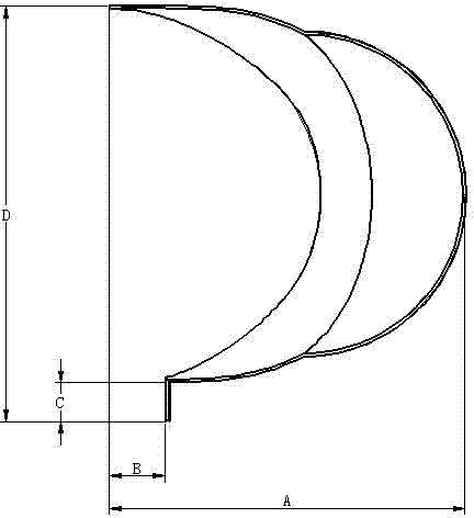
[0033] In the embodiment, according to the formed product formed by combining the six components of arc-shaped vertical wall, fastening hole, base wing, positioning hole, flat wing and expansion wing, its shape is as follows figure 2 shown.

[0034] figure 2 Among them, the components arranged in the order of labels are: arc vertical wall (1), fastening hole (2), basic wing (3), positioning hole (4), flat wing (5), expansion wing (6); Wherein, the number of positioning hole components (2) is 2, and the n...


PUM


Abstract

The invention relates to a wind-driven blade, in particular to a wind-driven accelerating wing with wind catching blades overlapped and capable of extending kinetic moment. The wind-driven accelerating wing comprises an arc-shaped vertical wall, a tightening hole, a basic wing, positioning holes, a flat wing and an extending ring. According to principles of natural wind energy, fluid power, resistance of flowing around objects an the like, the defects of low wind energy utilization efficiency, short moment, large structure, incapability of utilizing natural wind power and the like of conventional wind-driven blades are overcome, and the wind-driven accelerating wing which is long in kinetic moment, high in reliability, small in resistance and free of wind power grid prohibition is formed, has the advantages of simplicity in implementation and easiness in manufacturing, is attractive and elegant in structure, firm, durable and convenient to use, and has broad market space and high economic added value.

Description

technical field [0001] The invention relates to a wind energy power blade, in particular to a wind energy power acceleration wing which overlaps use of wind blades and can prolong the dynamic moment. Background technique [0002] Wind energy power wing, also known as "wind energy fan blade", refers to a physical device that obtains mechanical kinetic energy by intercepting natural wind force. At present, the known wind power wings generally have various forms such as wheel type, sail type, fan type, and propeller type. Although these forms can convert the energy generated by air movement into mechanical energy, they also have low utilization efficiency and short torque. , large structure, can not fully utilize the defects such as natural wind force, thereby have influenced the use function, application range and socio-economic value of known wind energy power wing. [0003] Contents of the invention [0004] The purpose of the present invention is to overcome the defects...

Claims


Application Information

Patent Timeline
Patent Type & Authority Applications(China)
IPC IPC(8): F03D3/06F03D9/00F21S9/04
CPCY02E10/74Y02P70/50
Inventor 钟明华
Owner 钟明华
Why Eureka
Try Eureka