Supercharge Your Innovation With Domain-Expert AI Agents!

Protection device with over-temperature and over-current double-layer protection function

A double-layer protection, over-temperature and over-current technology, used in emergency protection devices, electrical components, circuits, etc., can solve problems such as cost increase, and achieve the effects of low cost, reduced product cost, and simple structure

Active Publication Date: 2013-11-20
DONGGUAN BETTER ELECTRONICS TECH
View PDF6 Cites 3 Cited by
  • Summary
  • Abstract
  • Description
  • Claims
  • Application Information

AI Technical Summary

Problems solved by technology

Usually we mainly rely on over-current, but with the emergence of multiple electrical and electronic products, a single over-current can no longer meet the needs of the market, and it is necessary to protect the product from over-temperature. If two protection components are used, the cost will be reduced. increase a lot

Method used


Image

  • Protection device with over-temperature and over-current double-layer protection function
  • Protection device with over-temperature and over-current double-layer protection function
  • Protection device with over-temperature and over-current double-layer protection function

Examples


Embodiment 1

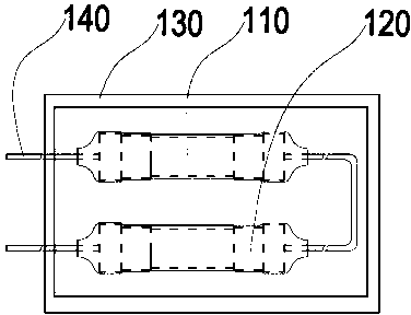
[0022] Embodiment 1 includes a protective box 130; one group includes two terminal electrodes 140 on the same side of the protective box 130, or two terminal electrodes 140 on both sides of the protective box 130, and at least one thermal fuse 110 connected in series between the two ends, Circuit arrangement with at least one current fuse 120 .

[0023] The protective box 130 forms a protective layer covering the cavity of the thermal fuse 110 and the current fuse 120 ; and two terminal electrodes 140 connected to the two ends and exposed outside the cavity of the protective box 130 .

[0024] A heat insulating layer is formed in the protection box 130 towards the direction of the circuit device. A ceramic substrate is disposed inside the protective box 130 .

[0025] In an embodiment, a separation layer is provided between the thermal fuse 110 and the current fuse 120 .

[0026] The temperature fuse 110 is arranged on the heat insulation layer of the inner layer of the prot...

Embodiment 3

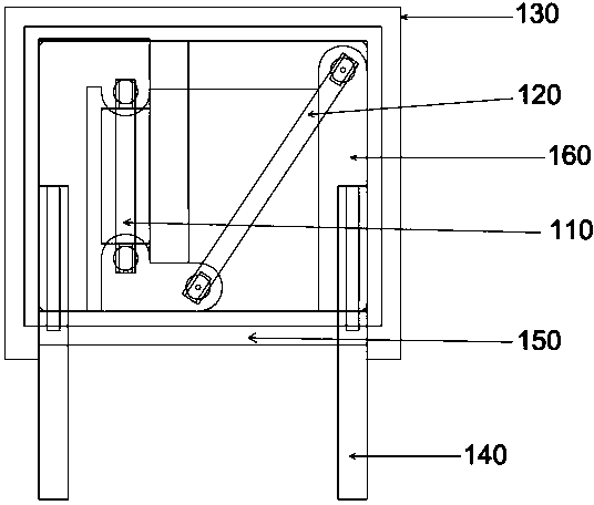
[0028] In embodiment three, see appendix image 3 As shown, the protection box 130 is provided with an opening on a side close to the terminal electrode 140 , and a base 150 is provided in the opening of the protection box 130 , and the terminal electrode 140 is disposed on the base 150 . The protective box 130 is provided with a conductive electrode or a pole plate 160, one end of the conductive electrode or pole plate 160 is connected to the terminal electrode 140, and the other end of the conductive electrode or pole plate 160 is connected to the thermal fuse 110 or the current fuse 120, and the thermal fuse 110 and the current fuse 120 Form an included angle of 30-70°.

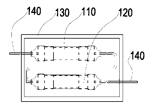
[0029] In the embodiment, when the above-mentioned current fuse 120 and the temperature fuse 110 are overlapped and arranged up and down, they can be displaced from each other, and terminal electrodes 140 are formed on both sides of the protective box 130 (for the second embodiment, refer to the attached ...


PUM


Abstract

The invention discloses a protection device with an over-temperature and over-current double-layer protection function, particularly a double-protection element structure. A requirement on the simultaneous protection of over-temperature and over-current can be met. The protection device comprises a protection box and a circuit device. Two terminal electrodes are arranged outside the protection box. The circuit device is arranged between the two terminal electrodes, and is formed by connecting in series at least one temperature fuse with at least one current fuse. The protection box forms a protective layer of a chamber covering the temperature fuse and the current fuse. The protection device is low in cost and convenient to mount, and is provided with double-layer protection fuses, the conventional circuit design is simplified, the machining process of an electronic circuit element is shortened, and the cost of a product is lowered.

Description

technical field [0001] The present invention relates to a circuit protection element, and more particularly relates to a protection device structure with over-temperature and over-current double-layer protection. Background technique [0002] At present, in the process of circuit design, we will always consider the safety protection of the circuit. In order to avoid danger or damage to electronic products during use, circuit protection components such as fuses will be added to the circuit. Usually we mainly rely on over-current, but with the emergence of multiple electrical and electronic products, a single over-current can no longer meet the needs of the market, and it is necessary to protect the product from over-temperature. If two protection components are used, the cost will be reduced. increase a lot. Contents of the invention [0003] The purpose of the present invention is to overcome the deficiencies of the prior art and provide an over-temperature and over-curre...

Claims


Application Information

Patent Timeline
Patent Type & Authority Applications(China)
IPC IPC(8): H01H85/055H01H85/165
Inventor 高连忠郭良华
Owner DONGGUAN BETTER ELECTRONICS TECH
Features
  • R&D
  • Intellectual Property
  • Life Sciences
  • Materials
  • Tech Scout
  • Unparalleled Data Quality
  • Higher Quality Content
  • 60% Fewer Hallucinations
Learn More