
Solar panel tightening device

A technology for fastening devices and solar panels, applied in photovoltaic power generation, electrical components, circuits, etc., can solve problems such as small adjustable range of bolts, easy adaptation problems, and increased management costs, so as to avoid adaptation problems, The effect of reducing management costs and improving stability

Active Publication Date: 2013-11-20
XIAMEN HOPERGY PHOTOVOLTAIC TECH
View PDF5 Cites 5 Cited by
  • Summary
  • Abstract
  • Description
  • Claims
  • Application Information

AI Technical Summary

Problems solved by technology

The problem with this is that, limited by the height of the accommodation space, the length of the bolts that can pass through the block is limited, so that the adjustable range of the bolts is small. When installing solar panels with different thicknesses, it is necessary to calculate the required bolt length and make corresponding selections. configuration, which is prone to adaptation problems and increased management costs
In addition, when assembling, it is necessary to use tools or fix the blocks by hand to lock the bolts. The installation is complicated and time-consuming.

Method used


Image

  • Solar panel tightening device
  • Solar panel tightening device
  • Solar panel tightening device

Examples


Embodiment 1

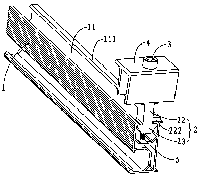
[0033] Such as figure 1 As shown, the solar panel fastening device includes a guide rail 1, a clip 2, a bolt 3, a pressure plate 4 and a spring 5, wherein:

[0034] The upper end of the guide rail 1 is provided with a block accommodating groove 11 , and the opening ends of the block accommodating groove 11 each have a retaining edge 111 extending inward.

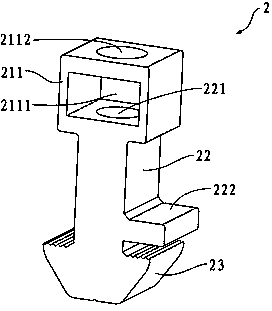
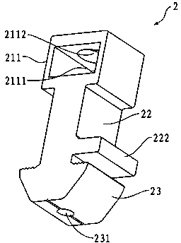
[0035] see figure 2 and image 3 , the upper part of the clamping part 2 is a bolt connection part, the middle part of the clamping part 2 is a bolt adjusting part 22 provided with a bolt accommodating space, and the lower part of the clamping part 2 is a block part 23 .

[0036] The bolt connection part includes a connection part body 211 and a nut (not shown in the figure), the nut is located in the cavity 2111 in the connection part body 211, the cavity 2111 is connected with the bolt accommodation space of the bolt adjustment part 22, and the connection part body 211 A through hole 2112 is opened in the center of the...

Embodiment 2

[0049] The difference between this embodiment and the first embodiment lies in the structure of the bolt adjusting part 22 . see Figure 7 , in this embodiment, the bolt adjusting part 22 includes two connecting plates 223 arranged symmetrically, and the through groove 224 formed between the two connecting plates 223 constitutes a bolt accommodating space, the width of the through groove 224 is smaller than the width of the nut, and the bolt One side of the adjusting portion 22 (ie, the outer side of one of the connecting plates 223 ) is provided with a supporting stopper 222 matched with the stopper edge 111 .


PUM


Abstract

The invention discloses a solar panel tightening device, which comprises a guide rail, a clamping piece, a bolt, a pressure plate and a spring, wherein a clamping block accommodating groove is formed at the upper end of the guide rail; a blocking lead extending inwards is formed at the tail end of the opening of the clamping block accommodating groove; the upper part of the clamping piece is a bolt connecting part; the middle part of the clamping piece is provided with a bolt adjusting part provided with a bolt accommodating space; the lower part of the clamping piece is a clamping block part; a spring mounting hole is formed in the center of the bottom end of the clamping block part; one side of the bolt adjusting part is provided with a support check block matched with the blocking edge; the distance between the support check block and the clamping block part is slightly larger than the thickness of the blocking edge; the bolt is in threaded connection with the bolt connecting part, and extends into the bolt adjusting part; the pressure plate is positioned above the clamping piece and connected with the clamping piece through the bolt; and the upper segment of the spring is fixedly connected in the spring mounting hole. The solar panel tightening device has the characteristics of easiness and convenience in installing and high universality.

Description

technical field [0001] The present invention relates to fastening devices, more particularly fastening devices for securing solar panels. Background technique [0002] As the core part of the solar power generation system, solar panels are used to convert the sun's radiant energy into electrical energy. Therefore, solar panels need to be installed outdoors, such as roofs, where they can fully receive sunlight. In order to receive more radiant energy, the surface area of ​​solar panels is large and mostly flat, which is greatly affected by wind, so its fixed installation structure needs to have strong positioning ability and structural strength. [0003] The Chinese patent with the patent number ZL200820102376.3 (publication number CN201197123Y) discloses a solar panel support structure, which includes a main beam and a clamping block. screw holes. When in use, the clamping block is placed in the accommodating space of the main girder, the pressing plate and the clamping bl...

Claims


Application Information

Patent Timeline
IPC IPC(8): H01L31/042
CPCY02E10/50
Inventor 姜丽萍
Owner XIAMEN HOPERGY PHOTOVOLTAIC TECH
Learn More