Adjustable clamp for rubber tensile set test

A technology of permanent deformation and test fixtures, which is applied in the direction of measuring devices, instruments, scientific instruments, etc., can solve the problems of non-adjustable fixture structure, large error of test results, and prone to disputes, so as to save test costs, ensure quality, and accurately adjust Effect of Rubber Tensile Length

Active Publication Date: 2015-11-11
CHINA RAILWAY LONGCHANG MATERIALS
View PDF5 Cites 10 Cited by
  • Summary
  • Abstract
  • Description
  • Claims
  • Application Information

AI Technical Summary

Problems solved by technology

[0003] The existing fixture structure is not adjustable, and it is difficult to accurately stretch to 1.5 times the original when stretching, resulting in large errors in test results and prone to disputes; and the clamping speed is slow

Method used


Image

  • Adjustable clamp for rubber tensile set test
  • Adjustable clamp for rubber tensile set test
  • Adjustable clamp for rubber tensile set test

Examples


Embodiment Construction

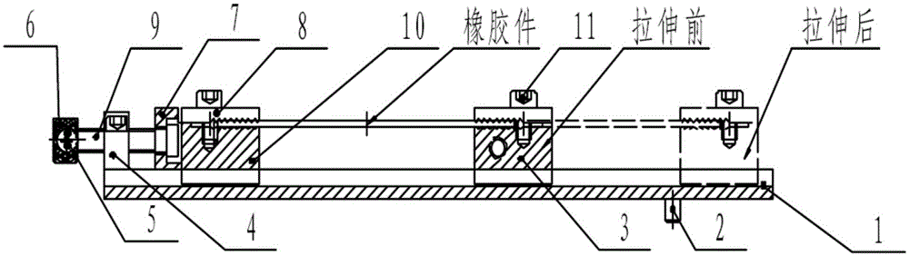
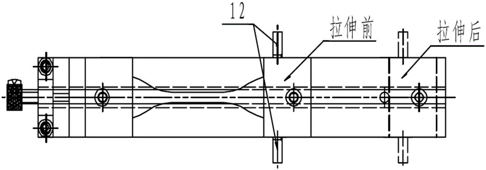
[0013] An adjustable rubber tensile set test fixture, such as figure 2 and image 3 As shown, it includes: track bottom plate 1, positioning pin 2, moving slider (coarse adjustment slider) 3, baffle plate 4, cross keyway screw 5, handle 6, backing plate 7, toothed cover plate 8, adjusting screw rod 9, Moving slider (fine adjustment slider) 10, hexagon socket head cap screw 11, tension rod 12, etc., wherein:

[0014] On the track base plate 1, there is a through dovetail groove 13 milled, which cooperates with the dovetail seat provided on the bottom surface of the fine adjustment slide block 10 and the coarse adjustment slide block 3 (such as Figure 4 shown), so that the fine adjustment slider 10 and the coarse adjustment slider 3 can slide freely on the track bottom plate; the fine adjustment slider 10 and the coarse adjustment slider 3 are all provided with a cover plate 8 through an inner hexagonal screw 11, and the In order to clamp the sample of rubber parts; in order...


PUM


Abstract

The invention discloses an adjustable clamp for a rubber tensile set test. The adjustable clamp comprises a track bottom plate, a fine adjustment sliding block and a rough adjustment sliding block, wherein the fine adjustment sliding block and the rough adjustment sliding block are arranged on the track bottom plate. The fine adjustment sliding block and the rough adjustment sliding block are provided with cover plates used for clamping a rubber piece sample, an adjusting screw penetrates through a step hole of a base plate and then is screwed into and penetrates out of a baffle, the base plate is fixed to the outer side of the fine adjustment sliding block, and the baffle is fixed to the track bottom plate. The adjustable clamp has the advantages that the rubber piece sample can be rapidly and quickly stretched to the distance 1.5 times of the original distance, and thus the accurate deformation amount can be obtained. By means of the clamp, test data (the rubber deformation amount) can be accurately obtained, and the positioning speed of test clamping can be increased; meanwhile, multiple adjustable clamps for the rubber tensile set test and samples can be put in a test box, so that the utilization rate of test equipment is greatly increased, the test efficiency is effectively improved, and a large amount of test cost is also saved.

Description

technical field [0001] The invention relates to a fast test jig for a rubber backing plate of a high-speed railway fastener used in a tensile permanent deformation test of the rubber backing plate. Background technique [0002] my country's high-speed railways now use rubber pads in the fastener system, which need to be made figure 1 For the shape of the sample, it is necessary to draw two lines 25mm apart in area A, then stretch the rubber with a jig, and pull the two lines 25mm apart to 1.5 times the original distance (ie 37.5mm), and then put it into the aging box for testing , after the aging box test, the fixture is removed, and the distance L of the original 25mm gauge line is recorded, so as to obtain the tensile permanent deformation rate. [0003] The existing fixture structure is not adjustable, and it is difficult to accurately stretch to 1.5 times the original when stretching, resulting in large errors in test results and prone to disputes; and the clamping spee...

Claims


Application Information

Patent Timeline
Patent Type & Authority Applications(China)
IPC IPC(8): G01N3/04
Inventor 范方亮冯斌张洪斌张小兵
Owner CHINA RAILWAY LONGCHANG MATERIALS
Why Eureka
Try Eureka