Load maintaining control valve

A load holding and control valve technology, applied in fluid pressure actuating devices, servo motor components, mechanical equipment, etc., to solve problems such as poor holding effect, difficulty in completely isolating the pilot spool valve from the main valve, and controlling oil circuit leakage. , to reduce the number of parts, facilitate promotion and use, and avoid the effect of sliding valve cooperation

Active Publication Date: 2018-12-11
XIAN FLIGHT SELF CONTROL INST OF AVIC
View PDF10 Cites 10 Cited by
  • Summary
  • Abstract
  • Description
  • Claims
  • Application Information

AI Technical Summary

Problems solved by technology

The main valve structure of the existing load holding control valve is generally a cone seal to achieve a good sealing effect, and the pilot structure is generally a slide valve structure to facilitate oil circuit switching under low pressure control and high pressure. It is difficult to completely isolate, resulting in leakage of the high-pressure holding oil circuit to the control oil circuit through the clearance of the pilot spool valve, which makes the holding effect worse
Although small leakage can be achieved through high-precision fit or complex structure, it will bring problems of high cost or complex structure and large installation space

Method used


Image

  • Load maintaining control valve
  • Load maintaining control valve
  • Load maintaining control valve

Examples


Embodiment 1

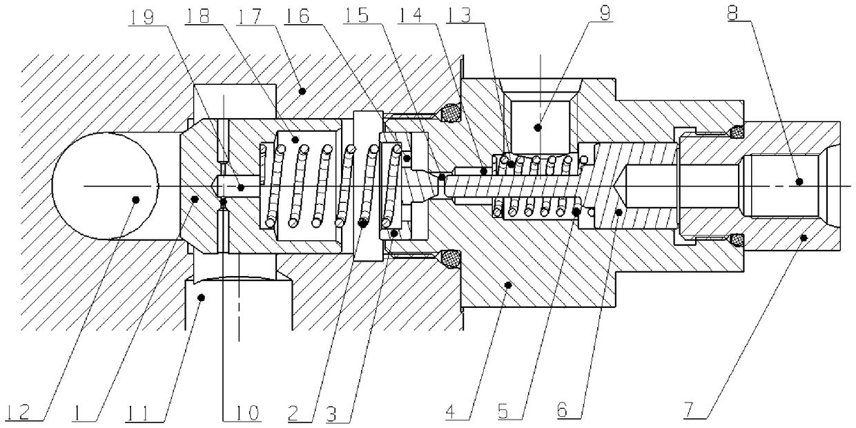
[0020] Embodiment 1 of the present invention discloses a double-cone sealed load-holding control valve. The control valve adopts pilot control and a plug-in structure, specifically as figure 2 As shown, including: 1-main spool, 2-main spring, 3-control spool, 4-control valve body, 5-pilot spring, 6-pilot push rod, 7-limit joint, 8-pilot oil port , 9-oil drain port, 10-throttle hole, 11-holding oil port, 12-oil inlet hole, 15-control valve hole, 16-oil hole and 17-installation valve body, wherein the valve is inserted On the 17-installation valve body, and 11-maintain oil port and 12-oil inlet hole are the oil ports on the 17-installation valve body. 1-The conical surface of the main valve core is in contact with the sealing surface between the 12-oil inlet port and 11-maintaining oil port of the valve body installed on 17-to form the conical surface sealing structure of the main valve port; 3-The cylindrical guide section of the control spool Cooperate with the guide hole at...

Embodiment 2

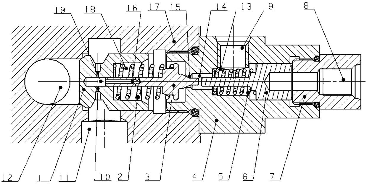
[0024] Embodiment 2 of the present invention discloses a double-cone sealed load-holding control valve. The control valve adopts pilot control and a plug-in structure, specifically as image 3 As shown, including: 1-main spool, 2-main spring, 3-control spool, 4-control valve body, 5-pilot spring, 6-pilot push rod, 7-limit joint, 8-pilot oil port , 9-Oil drain port, 10-Throttle hole, 11-Holding oil port, 12-Oil inlet hole, 13, 18-Second spring chamber, 14-19-Second oil passage hole, 15-Control valve hole , 16-oil hole and 17-installation valve body, wherein the valve is inserted on the 17-installation valve body, and 11-holding oil port and 12-oil inlet hole are the oil ports on the 17-installation valve body . 1-The conical surface of the main valve core is in contact with the sealing surface between the 17-installation valve body 12-the oil inlet hole and 11-the maintenance oil port to form the conical surface sealing structure of the main valve port; 3-The left end of the c...


PUM


Abstract

The invention belongs to a hydraulic control technology, and particularly relates to a load maintaining control valve. The load maintaining control valve is capable of, through designing a relative conical surface structure of a main valve element and a control valve element and isolating a main valve element oil way and a pilot control oil way, realizing extremely low leakage performance, using alarge action area ratio structure of a pilot push rod and the control valve element to realize low-pressure control of a high-pressure main valve, and adequately using multi-functional integration ofan internal structure and each part structure of the main valve element to complete structure simplification and a compact design, reducing the number of parts and avoiding matching a high-precisionslide valve, thereby reducing processing cost. So a low-leakage requirement design and a cost reducing and structure compact design of the load maintaining control valve are completed well, and the load maintaining control valve has extensive application prospect.

Description

technical field [0001] The invention belongs to hydraulic control technology, in particular to a load holding control valve. Background technique [0002] In the field of construction machinery, the load holding control valve plays an important role. It must be able to meet the two-way flow capacity during normal operation, that is, the oil can directly open the valve port to pass through when it is working in the forward direction, and it needs to be opened by controlling the pressure when working in the reverse direction. The valve port allows the oil to pass through; when the work stops, the oil circuit is cut off to realize the pressure maintenance function behind the valve port. Because the valve is directly connected to the main oil circuit, it has the characteristics of high pressure and large flow, and it is generally a pilot control structure. The main valve structure of the existing load holding control valve is generally a cone seal to achieve a good sealing effe...

Claims


Application Information

Patent Timeline
Patent Type & Authority Applications(China)
IPC IPC(8): F15B13/02
CPCF15B13/02F15B13/027
Inventor 赵锋李锋张青苗张玮陈小磊
Owner XIAN FLIGHT SELF CONTROL INST OF AVIC
Why Eureka
Try Eureka