
External flash light, photo taking system and working method of external flash light

A working method and flash technology, applied in the field of flash, can solve problems such as the effect of taking pictures is very different, the performance of the flash is very different, and the LED light cannot be flashed frequently, and the effect of ensuring the color temperature is achieved.

Inactive Publication Date: 2013-11-20
曾金辉
View PDF6 Cites 23 Cited by
  • Summary
  • Abstract
  • Description
  • Claims
  • Application Information

AI Technical Summary

Problems solved by technology

[0004] The camera function of smartphones is very important. From the development of tens of thousands of pixels of COMS lenses on smartphones to today’s more than 10 million pixels, the camera function of smartphones has basically replaced digital card cameras. However, although smartphones are different from ordinary There is little difference in the pixels of the camera, but the effect of taking pictures is very different. One of the reasons is that the flash performance of the mobile terminal is quite different from that of the ordinary camera.
[0005] In addition, although today's high-end smartphones are equipped with an LED light as a flash and fill light for their lens, there are still the following shortcomings: the LED light can only fill light with one brightness and the brightness is far from enough; when the LED light is used for flash Can not strobe and flash brightness can not be adjusted, which often makes the obtained works distorted

Method used


Image

  • External flash light, photo taking system and working method of external flash light
  • External flash light, photo taking system and working method of external flash light

Examples


Embodiment Construction

[0032] Below in conjunction with accompanying drawing and specific embodiment the present invention is described in further detail:

[0033] The external flash light of the present invention is placed outside the smart device with the camera function, where the smart device refers to a smart phone, tablet computer, etc. with the camera function, and the smart phone (equipped with APP / IOS software) is used as the following As an example, the composition and structure of the external flash are described.

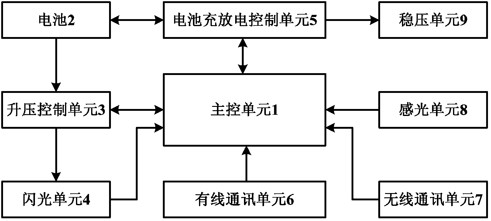
[0034] refer to figure 1 , the external flash includes a main control unit 1, and a communication unit, a photosensitive unit 8, a flash unit 4 and a power supply unit that are respectively communicatively connected to the main control unit 1, and the power supply is also electrically connected to the flash unit 4, while Power supply for main control unit 1 and flash unit 4.

[0035] Specifically, the power supply unit includes a battery 2, a battery charging and discharging...


PUM


Abstract

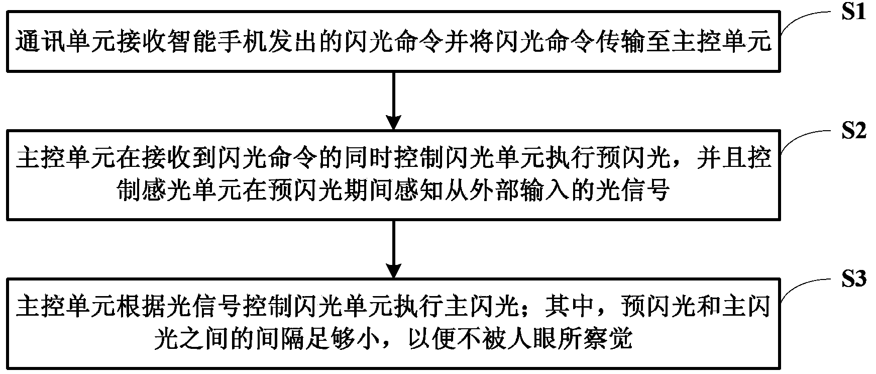
The invention discloses an external flash light, a photo taking system and a working method of the external flash light. The external flash light arranged on the exterior of smart equipment with a photo taking function comprises a main control unit, a communication unit, a light sensing unit, a flash unit and a power unit, wherein the communication unit is used for receiving a flash command sent out by the smart equipment and transmitting the flash command to the main control unit; the light sensing unit is used for sensing a light signal input from the exterior and transmitting the light signal to the main control unit; the power unit is used for providing the main control unit and the flash unit with power; and moreover, when receiving the flash command, the main control unit simultaneously controls the flash unit to flash according to the light signal. Since the real-time connection between the external flash light and the smart equipment is realized in a wire way or in a wireless way, a flash action made by the smart equipment as the smart equipment sends out the flash command is guaranteed; and when the flash intensity is determined via a mode that the external light intensity is perceived by a high-sensitivity light measuring probe, the flash index adjustment of the flash light according to the intensity of natural light can be easily realized.

Description

technical field [0001] The invention relates to the technical field of flashlights, in particular to an external flashlight, a photographing system and a working method of the external flashlight. Background technique [0002] At present, there is no external flash professionally used for smartphones. [0003] In recent years, with the rapid development of smart phones, the accessory functions equipped with smart phones are also becoming more and more perfect. Such as browsing the web, sending emails, taking photos and recording videos, etc. [0004] The camera function of smartphones is very important. From the development of tens of thousands of pixels of COMS lenses on smartphones to today’s more than 10 million pixels, the camera function of smartphones has basically replaced digital card cameras. However, although smartphones are different from ordinary There is little difference in the pixels of the camera, but the effect of taking pictures is very different. One of ...

Claims


Application Information

Patent Timeline
Patent Type & Authority Applications(China)
IPC IPC(8): H05B37/02G03B15/05
CPCY02B20/42Y02B20/48Y02B20/40
Inventor 曾金辉
Owner 曾金辉
Learn More