Cooperate with pneumatic workbench to realize circuit board rapid cycle plating fixture

A pneumatic workbench, rapid cycle technology, applied in printed circuits, printed circuit manufacturing, electrical components, etc., can solve problems such as removing splints, product wrinkling and scrapping, etc., to improve production efficiency and improve product quality.

Active Publication Date: 2016-03-23
JIANGSU HUASHEN ELECTRONICS
View PDF5 Cites 0 Cited by
  • Summary
  • Abstract
  • Description
  • Claims
  • Application Information

AI Technical Summary

Problems solved by technology

[0007] In order to overcome the above-mentioned defects, the present invention provides a jig for rapid cycle electroplating of circuit boards in conjunction with a pneumatic workbench. Wrinkled and scrapped

Method used


Image

  • Cooperate with pneumatic workbench to realize circuit board rapid cycle plating fixture
  • Cooperate with pneumatic workbench to realize circuit board rapid cycle plating fixture
  • Cooperate with pneumatic workbench to realize circuit board rapid cycle plating fixture

Examples


Embodiment Construction

[0024] In conjunction with the accompanying drawings, the present invention is described in detail, but the scope of protection of the present invention is not limited to the following examples, that is, all simple equivalent changes and modifications made with the patent scope of the present invention and the content of the specification are still patents of the present invention. covered.

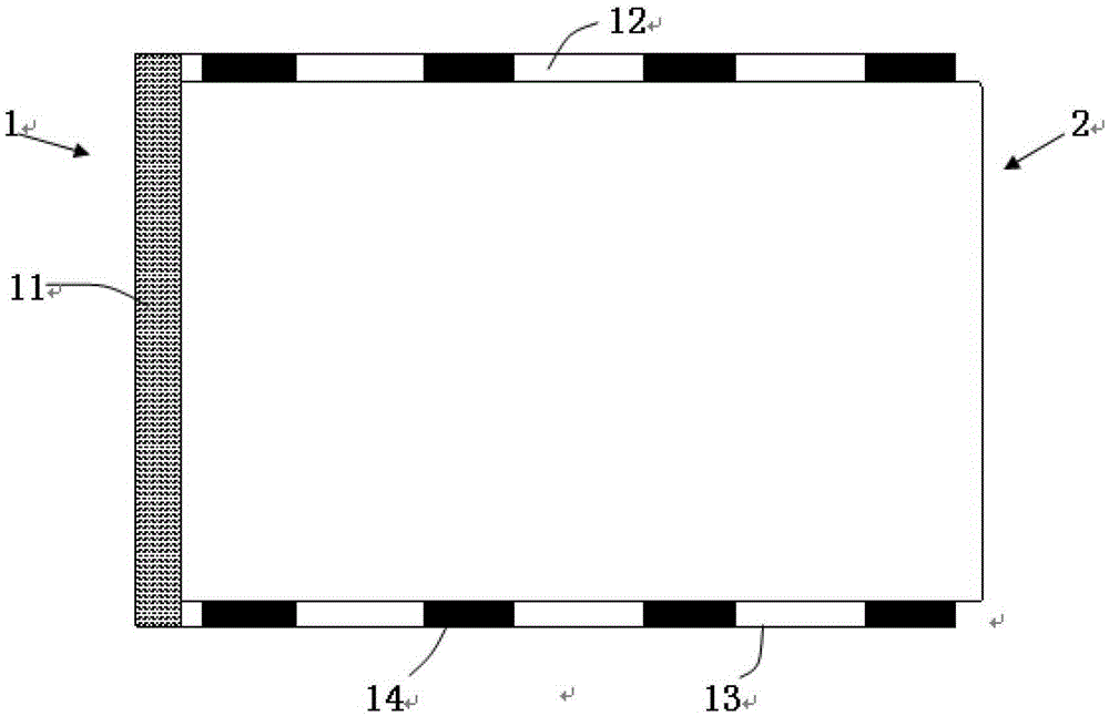
[0025] In this embodiment, the jig for fast cycle electroplating of circuit boards is realized by cooperating with the pneumatic workbench. The pneumatic workbench (not shown in the figure) includes a stepping device and a work surface:

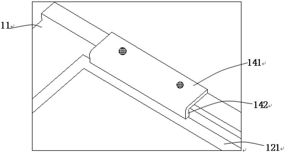
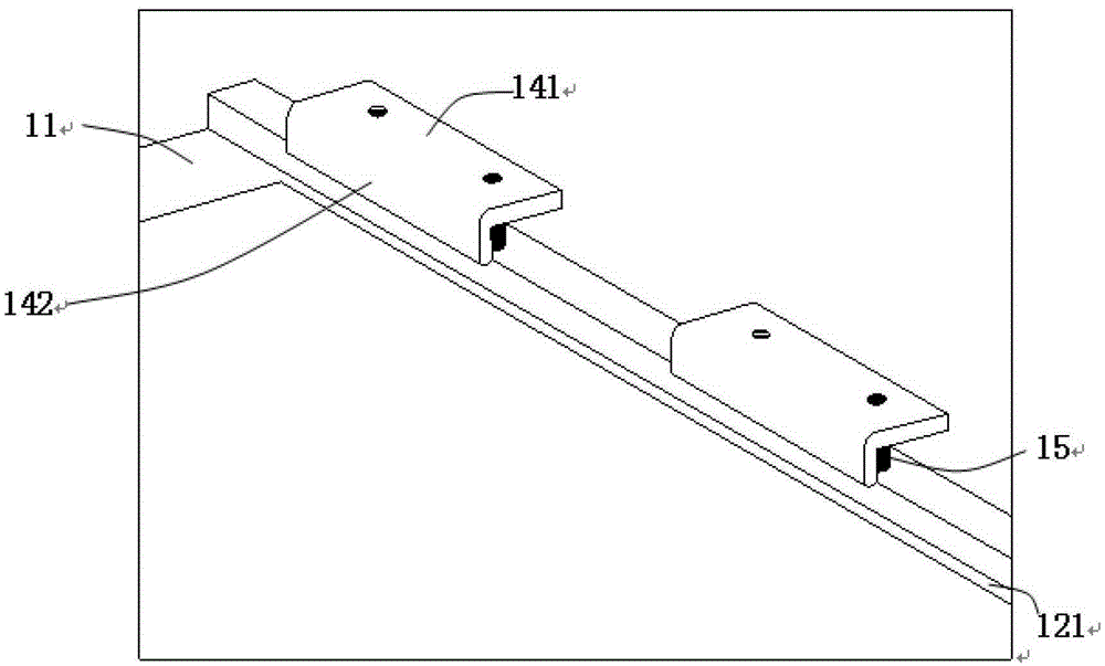
[0026] The working surface is provided with grooves (not shown) that are used to cooperate with the layout of the clamps, and the clamps can be fixed on the working surface through the grooves. The clamps are a frame 1 that matches the specifications of the circuit board 2. The size of the frame 1 can be According to the size setting of the circuit board...


PUM


Abstract

The invention discloses a clamp for quickly and circularly electroplating a circuit board by matching a pneumatic worktable. The pneumatic worktable comprises a pedaling device and a worktable board, wherein the worktable board is provided with a groove for matching and arranging the clamp. The clamp comprises a frame (1) matched with a circuit board (2) in specification, and the frame can support the circuit board. At least two fixed parts are arranged at the edge of the frame, and the fixed parts can constraint and compress the circuit board and is lifted up through the stressed pedaling device so as to release the clamp. After the clamp is implemented, the problem that the clamping plate is removed and discharged by a lot of manpower is solved. Meanwhile, the problem that a product is cockled and scrapped due to the operating proficiency degree of staff is further solved.

Description

technical field [0001] The invention relates to an auxiliary tool for circuit board electroplating, in particular to a clamp for a pneumatic workbench to realize rapid cycle electroplating of a circuit board. Background technique [0002] During the electroplating process of the circuit board, it is often necessary to manually clamp the circuit board with a fixture and place it into the electroplating tank. The following steps are usually used in actual operation: [0003] 1) Prepare a desktop with a smooth, clean surface and no sundries / foreign objects. First, place the frame on one side on the table, and then gently lay the board on the frame; when laying the board on the frame, you should Make sure that the target holes or slicing holes at the four corners of the board are just in the frame, so as to ensure that the position in the forming area will not be caught by the frame; do not move the placed board and frame, and gently cover the other side of the frame on the boar...

Claims


Application Information

Patent Timeline
Patent Type & Authority Patents(China)
IPC IPC(8): H05K3/00
Inventor 李华团杨小林朱灿华梅磊陆清
Owner JIANGSU HUASHEN ELECTRONICS
Why Eureka
Try Eureka