

Interior part for vehicle
An interior and component technology, applied in the field of vehicle interior parts, can solve the problems of threaded components falling off and time-consuming, and achieve the effects of being easy to fall and easy to hang.
- Summary
- Abstract
- Description
- Claims
- Application Information
AI Technical Summary
Problems solved by technology
Method used
Image

Examples
Embodiment
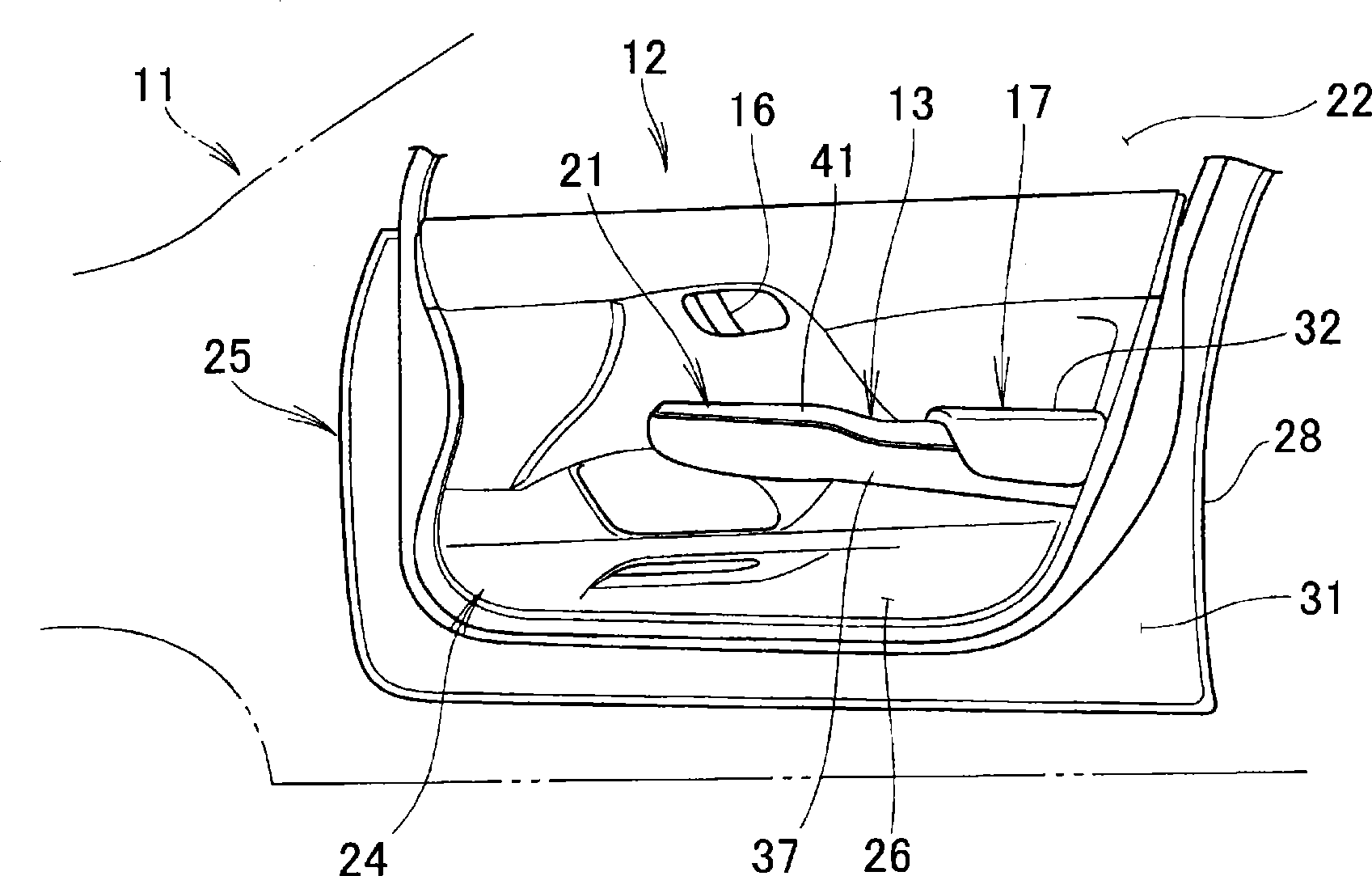
[0027] figure 1 , figure 2 and image 3 An interior component 13 provided in the vehicle body 11 is shown. The door 12 is a right front door and has a door opening handle 16 , an armrest 17 , and an operation panel 21 arranged on the armrest 17 . Buttons for opening and closing a glass 22 of the right front door 12 and a door glass of a left front door (not shown) are arranged on the operation panel 21 .
[0028] The door 12 has a storage box as an interior member 13 arranged on an armrest 17 , and a speaker arrangement portion 24 . A door trim wall 26 is attached to the door main body 25 . The door body 25 is composed of an outer panel 28 and an inner panel 31 . The door trim wall 26 , the trim component 13 and the armrest 17 are fixed on the inner panel 31 .
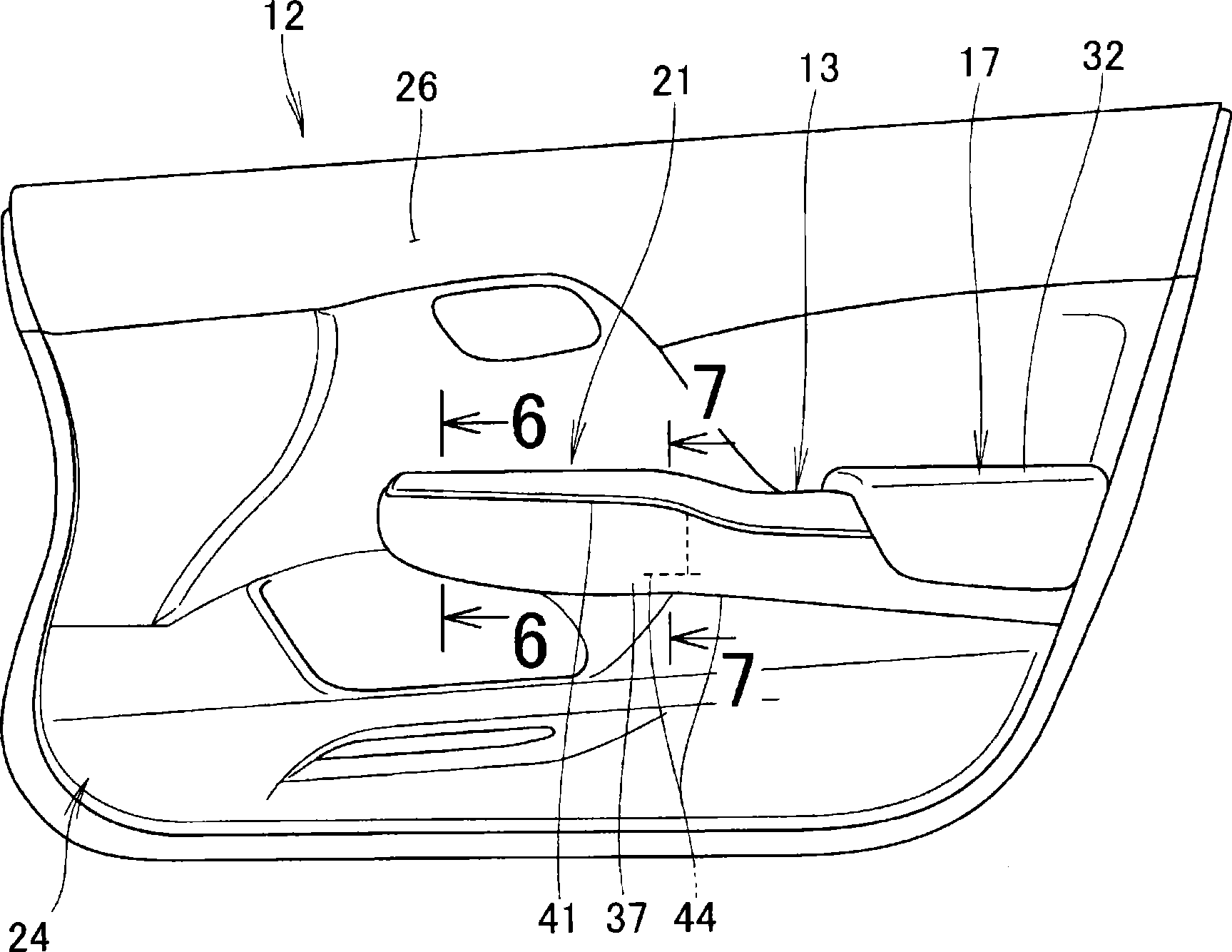
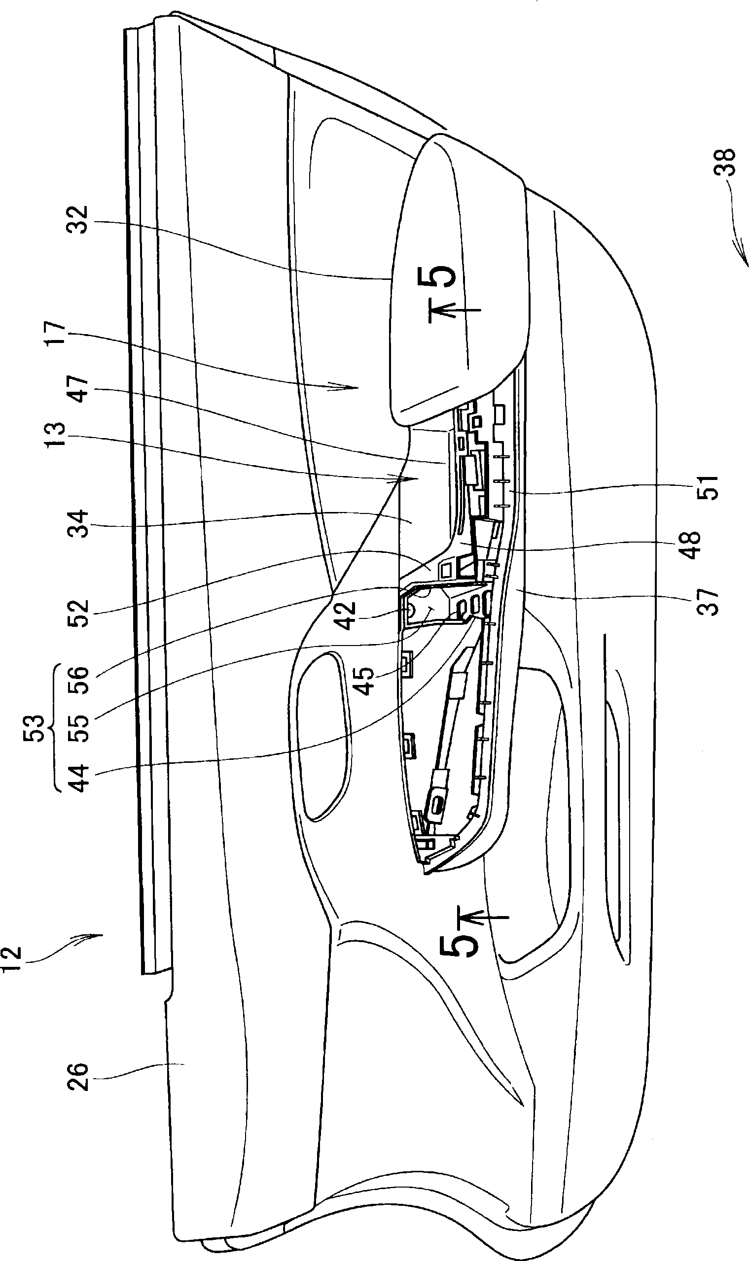
[0029] Such as Figure 1 to Figure 7 As shown, the armrest 17 has an armrest body portion 32 extending from the door trim wall 26 ( Figure 6 Arrow a1 direction of ), which is formed by placing the elbow. Suc...
PUM
 Abstract
Description
Claims
Application Information