Driver device, driving method, and display device
The technology of a driving device and driving method, which is applied in the direction of static indicators, instruments, electrical components, etc., can solve the problems of insufficient capacity, reduced charging rate of pixel electrodes, insufficient charging of pixel electrodes, etc., and achieve the goal of reducing load and increasing aperture ratio Effect
- Summary
- Abstract
- Description
- Claims
- Application Information
AI Technical Summary
Problems solved by technology
Method used
Image
Examples
Embodiment approach 1
[0067] refer to Figure 1 to Figure 7 A driving device according to an embodiment of the present invention, a display device including the driving device, and a driving method thereof will be described. However, the configurations described in this embodiment are not intended to limit the scope of the present invention, but are merely illustrative examples, unless there are particularly specific descriptions.
[0068] (Configuration of display device)
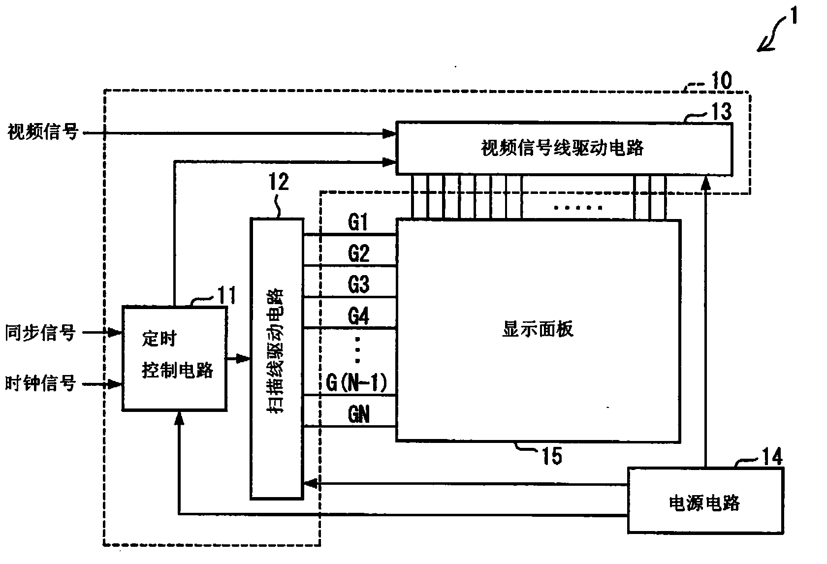
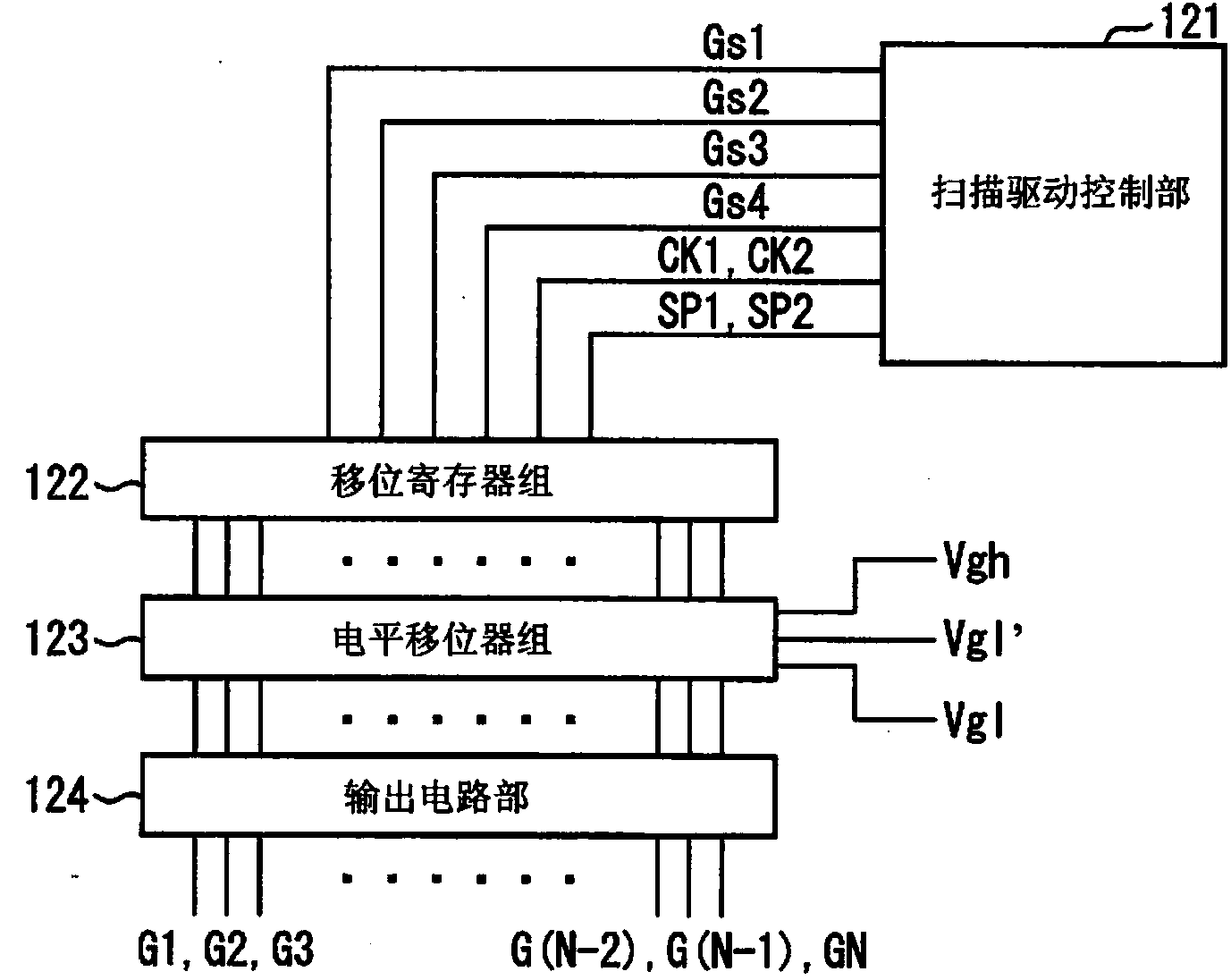
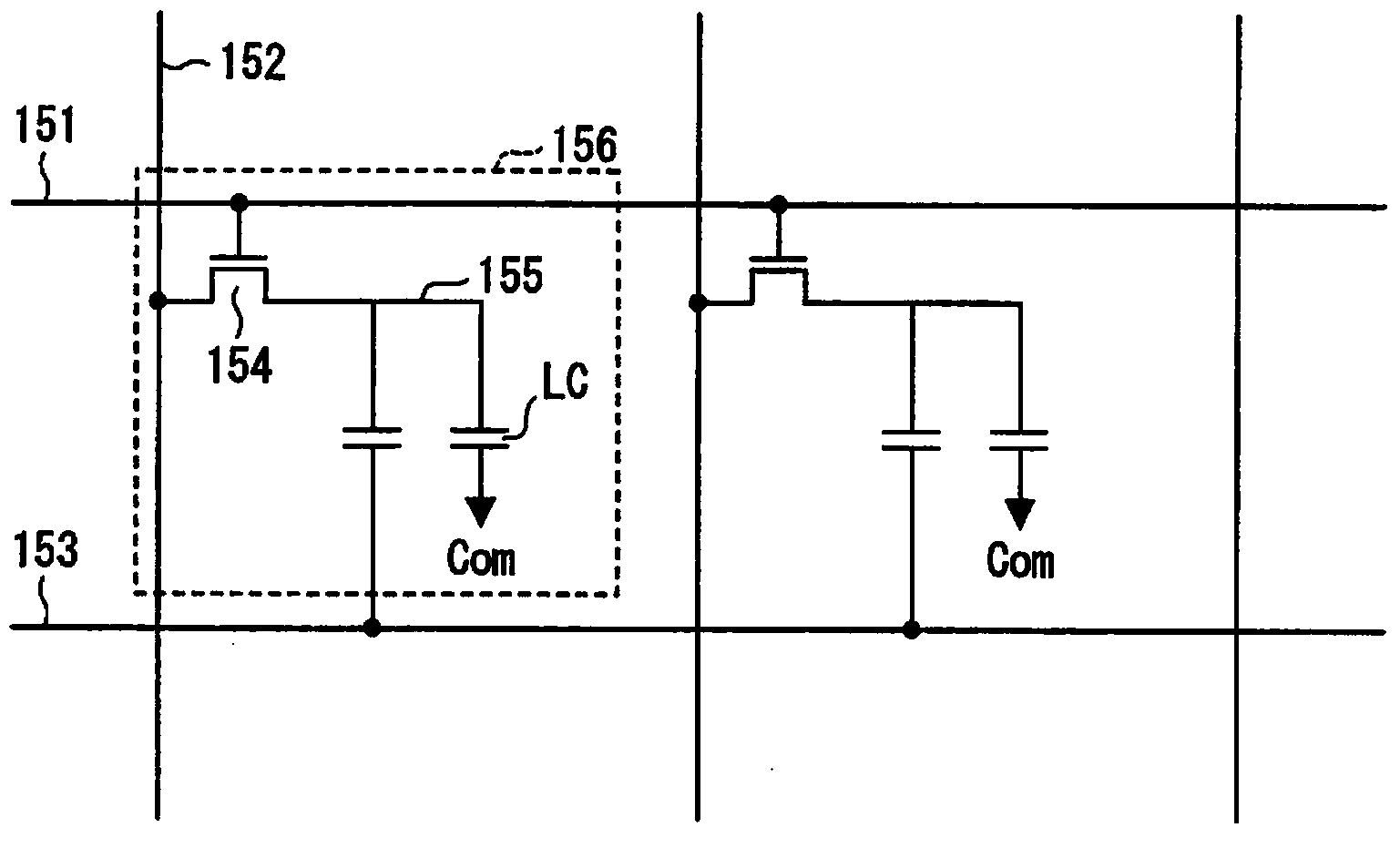
[0069] refer to Figure 1 to Figure 3 The display device of this embodiment will be described. First refer to figure 1 The configuration of the display device 1 of this embodiment will be described. figure 1 It is a block diagram showing the main configuration of the display device 1 of the present embodiment.
[0070] Such as figure 1 As shown, the display device 1 includes: a driving device 10 including a timing control circuit 11 , a scanning line driving circuit 12 , and a video signal line driving circuit 13 ; a pow...
Embodiment approach 2
[0135] In Embodiment 1, the first scan of the n+1th scan line 151 is performed overlapping the scan of the nth scan line 151, and the n+th scan is performed when the scan of the nth scan line 151 ends. The configuration of the second scan of one scan line 151 has been described as an example, but the present invention is not limited thereto. For example, the first scan of the n+m (wherein, m is an integer other than 0) scan line 151 may be overlapped with the scan of the n scan line 151, and when the scan of the n scan line 151 ends At this point in time, the second scan of the (n+m) scan line 151 is performed.
[0136] refer to Figure 9 The case where m=2 in this embodiment will be described. Figure 9 It is a timing chart showing the relationship between the scan signal and the video signal in the second embodiment.
[0137] Such as Figure 9 As shown, the scanning line driving circuit 12 overlaps the scanning signal Gn scanning the nth scanning line 151 and executes th...
Embodiment approach 3
[0140] In Embodiment 1, a configuration in which the first scanning of the n+1-th scanning line 151 is performed overlapping with the scanning of the n-th scanning line 151 regardless of the polarity of the video signal has been described as an example. The present invention is not limited thereto. For example, a configuration may be adopted in which the first scan is executed only when the polarity of the supplied video signal is reversed.
[0141] refer to Figure 10 In this embodiment, when the polarity of the supplied video signal is reversed, the first scan is performed overlapping with the scan of the n-th scanning line, and when the polarity of the video signal is not reversed, from When the scanning of the n-th scanning line ends, only the second scanning is performed. Figure 10 It is a timing chart showing the relationship between the scan signal and the video signal in this embodiment.
[0142] Such as Figure 10 As shown, the polarity of the video signal S1 sup...
PUM
 Abstract
Description
Claims
Application Information
 - R&D
- Intellectual Property
- Life Sciences
- Materials
- Tech Scout
- Unparalleled Data Quality
- Higher Quality Content
- 60% Fewer Hallucinations
Browse by: Latest US Patents, China's latest patents, Technical Efficacy Thesaurus, Application Domain, Technology Topic, Popular Technical Reports.
© 2025 PatSnap. All rights reserved.Legal|Privacy policy|Modern Slavery Act Transparency Statement|Sitemap|About US| Contact US: help@patsnap.com


