Liquid crystal display device and display control method thereof

a display device and liquid crystal technology, applied in static indicating devices, instruments, optics, etc., can solve the problems of deteriorating image quality, unsatisfactory change in pixel charging time,

Inactive Publication Date: 2009-04-28
TOSHIBA MATSUSHITA DISPLAY TECH
View PDF10 Cites 2 Cited by
  • Summary
  • Abstract
  • Description
  • Claims
  • Application Information

AI Technical Summary

Benefits of technology

[0012]An object of the present invention is to provide a liquid crystal display device which can prevent pixels from being insufficiently charged due to the fluctuation of the horizontal period of a sync signal externally supplied together with a video signal, and a display control method thereof.
[0015]According to the liquid crystal display device and display control method, the length of the horizontal period is detected as the number of pulses of the reference clock signal, and the row selection period is adjusted based on the detected number of pulses obtained. Consequently, the pixels of each row are driven without occurrence of insufficient charging caused by fluctuation of the horizontal period of the sync signal. Accordingly, it is possible to prevent the quality of displayed images from deteriorating due to insufficiently charged pixels.

Problems solved by technology

However, since a horizontal period of the sync signal fluctuates depending on a reproduction process for the video signal, undesirable change in pixel charging time occurs according to a phase difference of the clock signal to the horizontal period of the sync signal.
This raises a problem that the quality of displayed images deteriorates due to insufficiently charged pixels.

Method used


Image

  • Liquid crystal display device and display control method thereof
  • Liquid crystal display device and display control method thereof
  • Liquid crystal display device and display control method thereof

Examples


Embodiment Construction

[0024]A liquid crystal display device according to one embodiment of the present invention will be described in more details with reference to the accompanying drawings.

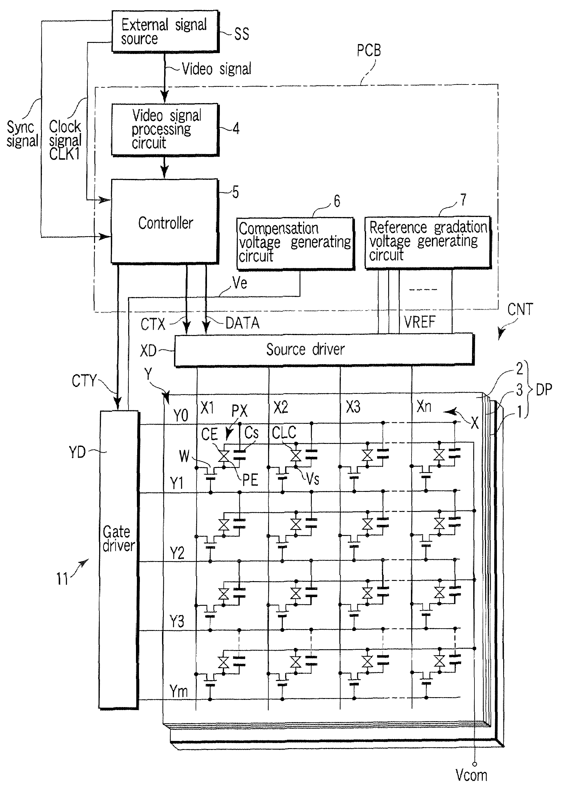
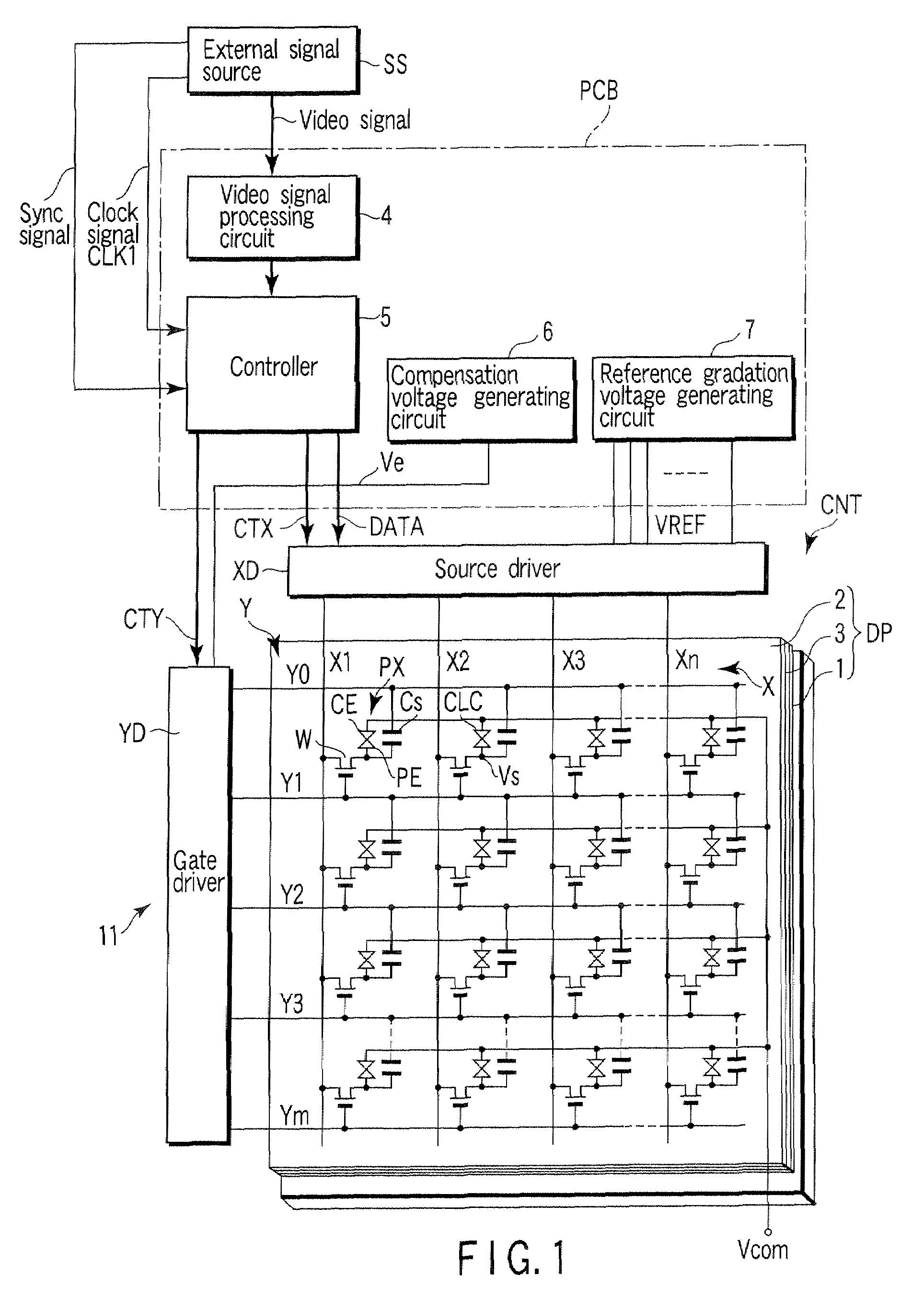
[0025]FIG. 1 schematically shows the circuit configuration of the liquid crystal display device 11 according to the embodiment. The liquid crystal display device 11 comprises an OCB-mode liquid crystal display panel DP, and a display control circuit CNT connected to the liquid crystal display panel DP. The liquid crystal display panel DP has a structure in which a liquid crystal layer 3 is held between an array substrate 1 and a counter substrate 2 which serve as a pair of electrode substrates. The liquid crystal layer 3 includes an OCB liquid crystal material whose liquid crystal molecules are transferred in advance from a splay alignment to a bend alignment to attain a normally-white display operation in an OCB mode and are prevented from being inverse-transferred from the bend alignment to the splay alignment by a...


PUM

PropertyMeasurementUnit
constant frequencyaaaaaaaaaa
lengthaaaaaaaaaa
timeaaaaaaaaaa

Abstract

A liquid crystal display device comprises a liquid crystal display panel including a plurality of pixels are arrayed substantially in a matrix, and a display control circuit which sequentially selects the rows of pixels in synchronism with a horizontal period of a sync signal externally supplied together with a video signal, and drives the pixels of a selected row in accordance with pixel data items obtained from the video signal for each horizontal period. The display control circuit includes a clock generator which generates a reference clock signal of a constant frequency, a period detector which detects a length of the horizontal period as the number of pulses of the reference clock signal, and a drive timing generator which adjusts a row selection period based on the number of pulses detected by the period detector.

Description

CROSS-REFERENCE TO RELATED APPLICATIONS[0001]This application is based upon and claims the benefit of priority from prior Japanese Patent Application No. 2005-175232, filed Jun. 15, 2005, the entire contents of which are incorporated herein by reference.BACKGROUND OF THE INVENTION[0002]1. Field of the Invention[0003]The present invention relates to a liquid crystal display device applied to a liquid crystal display panel of, for example, optically compensated bend (OCB) mode, and a display control method thereof.[0004]2. Description of the Related Art[0005]A flat-panel display device represented by a liquid crystal display device is widely utilized as display device for a computer, a car navigation system, a television receiver, etc.[0006]In general, the liquid crystal display device comprises a liquid crystal display panel that includes a matrix array of liquid crystal pixels, and a display control circuit that controls the display panel. The liquid crystal display panel has a stru...

Claims


Application Information

Patent Timeline
Patent Type & Authority Patents(United States)
IPC IPC(8): G02F1/1335
CPCG09G5/008G09G3/3648G09G2310/08G09G3/36G02F1/133G09G3/20
Inventor TERANISHI, KENTARO
Owner TOSHIBA MATSUSHITA DISPLAY TECH
Why Eureka
Try Eureka