
Automatic mold loading manipulator

A manipulator and mold loading technology, which is applied to manipulators, program-controlled manipulators, workshop equipment, etc., can solve problems such as low precision, low efficiency, time-consuming and labor-intensive, and achieve the effects of saving manpower, realizing information production, and improving efficiency

Active Publication Date: 2016-03-16
YUANDA RESIDENTIAL IND HANGZHOU CO LTD
View PDF8 Cites 0 Cited by
  • Summary
  • Abstract
  • Description
  • Claims
  • Application Information

AI Technical Summary

Problems solved by technology

At present, most domestic manufacturers position and place the ribs after manual measurement, and then use fixtures or bolts to fix them. This process is time-consuming and laborious, and it is prone to human errors and errors, with low efficiency and low precision.

Method used


Image

  • Automatic mold loading manipulator
  • Automatic mold loading manipulator
  • Automatic mold loading manipulator

Examples


Embodiment Construction

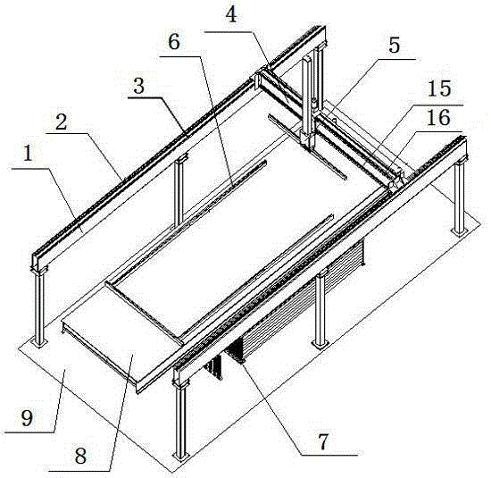
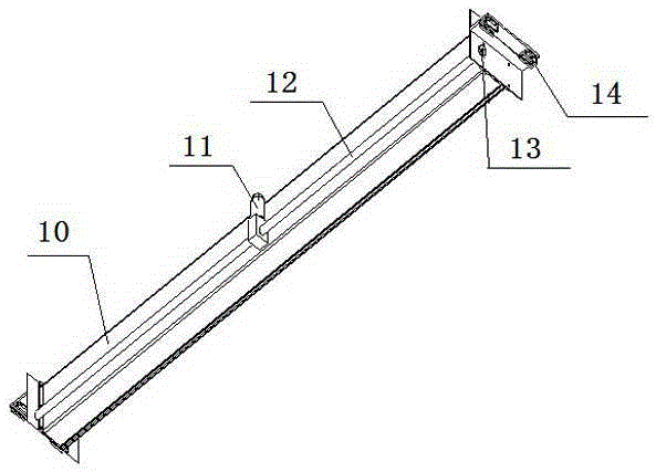
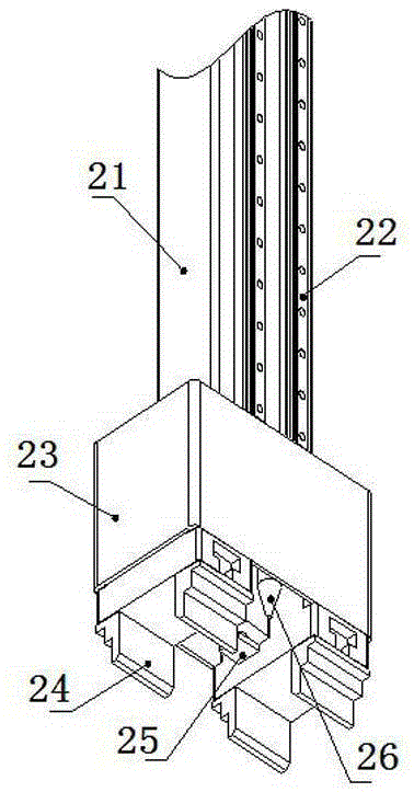
[0023] see figure 1 — Figure 4 , the automatic mold loading manipulator of the present invention includes an X-axis truss 1, a Y-axis girder 4 and a manipulator 5; the X-axis truss 1 has left and right guide longitudinal beams and support columns, and the upper ends of the support columns are connected and fixed to the guide longitudinal beams , the lower end of the supporting column is fixed on the ground, and the longitudinal linear guide rail and the longitudinal rack are installed on the guide longitudinal beam; The horizontal driving mechanism and the longitudinal driving mechanism are installed on the top, the slider is set on the longitudinal linear guide rail of the guiding longitudinal beam, the longitudinal driving mechanism is connected to the gear at the end of the transmission beam through the transmission rod, the gear meshes with the longitudinal rack on the guiding longitudinal beam, and the horizontal driving The mechanism is connected to drive the transvers...


PUM


Abstract

The invention discloses an automatic die setting manipulator, comprising an X-axis truss, a Y-axis girder and a manipulator body, wherein the X-axis truss is provided with left and right guide longitudinal beams and support vertical stand columns, and each guide longitudinal beam is provided with a longitudinal linear guide rail and a longitudinal rack; the Y-axis girder is structurally provided with a gear, a transverse rack, a transverse linear guide rail, a slider and the manipulator body; the manipulator body is provided with a transverse driving mechanism and a longitudinal driving mechanism, as well as a lifting arm, a precise rotating air cylinder, a lifting gear and a lifting driving mechanism which are installed on a manipulator frame; an integrated execution claw is provided with a pneumatic gripper, a pressure pin cylinder and a nozzle. The automatic die setting manipulator is capable of improving the efficiency of a production line and increasing the precision of prefabricated cement members to 1mm, saves manpower by virtue of mechanical and automatic operation, and is controlled by a computer in a whole process so that real-time information and progress of production can be controlled easily and information production is realized.

Description

technical field [0001] The invention relates to the technical field of construction machinery, in particular to an automatic mold loading manipulator. Background technique [0002] When producing cement prefabricated slabs, it is necessary to fix the mold retainer on the steel table according to the shape of the prefabricated slab, and then pour concrete. At present, most domestic manufacturers position and place the ribs after manual measurement, and then use fixtures or bolts to fix them. This process is time-consuming and laborious, and is prone to human errors and errors, with low efficiency and low precision. Contents of the invention [0003] The technical problem to be solved by the present invention is: to solve the problems of the above-mentioned prior art, and to provide an automatic mold loading manipulator, which can automatically install and position the mold ribs and draw the positioning lines of modules such as doors, windows and wire boxes on the steel tabl...

Claims


Application Information

Patent Timeline
Patent Type & Authority Patents(China)
IPC IPC(8): B25J9/02B25J9/12B25J15/00B25J15/06B25H7/04
Inventor 张剑陈韶临刘超
Owner YUANDA RESIDENTIAL IND HANGZHOU CO LTD
Learn More