
Security air system for preventing slag from entering blast furnaces

An air system and blast furnace technology, applied in blast furnaces, blast furnace details, blast furnace parts, etc., can solve problems such as abnormal blast furnace shutdown, increase in daily operating costs, and inability to operate automatically, and achieve the effect of highlighting substantive characteristics

Inactive Publication Date: 2013-11-27
JIGANG GRP
View PDF6 Cites 0 Cited by
  • Summary
  • Abstract
  • Description
  • Claims
  • Application Information

AI Technical Summary

Problems solved by technology

Shutdown due to failure of the fan system often leads to abnormal shutdown of the blast furnace or even slag filling
At present, some ironmaking plants have not taken any protective measures, and the blast furnace fan system is abnormal 2 to 3 times a year, which leads to the shutdown of the blast furnace due to slag filling at the tuyere, and the shutdown of the blast furnace and equipment maintenance have brought huge economic losses; Setting up a set of fan equipment for long-term operation to provide a security wind source, although it ensures the safety of the blast furnace operation, but the daily operating costs are significantly increased, automatic operation is not possible, and the staffing is redundant; there are also ironworks that draw security wind from a running blast furnace source, but it is impossible to achieve mutual protection between multiple blast furnaces, resulting in the protection range not being fully covered, which is the deficiency of the existing technology

Method used


Image

  • Security air system for preventing slag from entering blast furnaces
  • Security air system for preventing slag from entering blast furnaces

Examples


Embodiment Construction

[0017] In order to clearly illustrate the technical features of the solution, the solution will be described below through a specific implementation mode combined with the accompanying drawings.

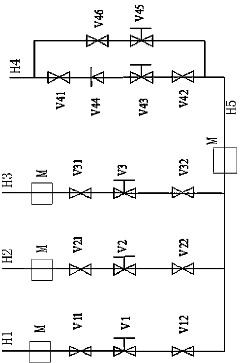
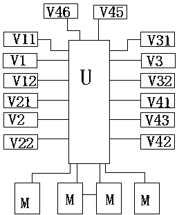
[0018] It can be seen from the attached drawings that the safety wind system for preventing blast furnace slag filling in this scheme includes three 1750m 3 Blast furnace air supply pipes H1, H2, H3, one 3200 m 3 Blast furnace air supply pipe H4, a ventilation pipe H5 respectively connected with the 1750m 3 Blast furnace air supply pipelines H1, H2, H3 are connected, and the ventilation pipeline H5 is connected with the 3200 m 3 Blast furnace air supply pipeline H4 connected, the first 1750m 3 The blast furnace air supply pipeline H1 is equipped with a pressure transmitter M, a pipeline butterfly valve V11, a pipeline butterfly valve V12 and an electric quick-opening valve V1. The pipeline butterfly valve is an electric butterfly valve, and the second 1750m 3 Blast furnace air sup...


PUM


Abstract

The invention provides the technical scheme of a security air system for preventing the slag from entering blast furnaces. The security air system comprises three 1750m<3> blast furnace air supply pipelines, one 3200m<3> blast furnace air supply pipeline and a ventilation pipeline, wherein the ventilation pipeline is communicated with the 1750m<3> blast furnace air supply pipelines respectively and is also communicated with the 3200m<3> blast furnace air supply pipeline, all the 1750m<3> blast furnace air supply pipelines are provided with pressure transmitters, pipeline butterfly valves and electronic quick-opening valves, the ventilation pipeline is provided with a pressure transmitter, the 3200m<3> blast furnace air supply pipeline is communicated with the ventilation pipeline through a first passage and a second passage respectively, each of the first passage and the second passage is provided with an air supply butterfly valve, a first pipeline is further provided with a check valve and a pneumatic quick-opening valve, and the second passage is further provided with a regulating valve. According to the technical scheme, the automatic introduction of the security air among a plurality of blast furnaces can be achieved according to the variation condition of the air pressure without the need of arranging fan equipment independently, and the phenomenon that slag enters the blast furnaces due to abnormal stop of the blast furnaces is effectively prevented.

Description

technical field [0001] The invention relates to a device used in ironmaking blast furnace technology, in particular to a safety wind system for preventing blast furnace from filling slag. Background technique [0002] In the prior art, it is known that the blast furnace air supply system is an important part of the ironmaking process and an important guarantee for the safe production of the blast furnace. Shutdown due to failure of the fan system often leads to abnormal shutdown of the blast furnace or even slag filling. At present, some ironmaking plants have not taken any protective measures, and the blast furnace fan system is abnormal 2 to 3 times a year, which leads to the shutdown of the blast furnace due to slag filling at the tuyere, and the shutdown of the blast furnace and equipment maintenance have brought huge economic losses; Setting up a set of fan equipment for long-term operation to provide a security wind source, although it ensures the safety of the blast ...

Claims


Application Information

Patent Timeline
IPC IPC(8): C21B9/10
Inventor 张永护王炜吴晓磊王官辉曹军礼张卫东王超饶丽慧
Owner JIGANG GRP
Learn More