an engine fuel injector

A fuel injector and engine technology, used in engine components, machines/engines, mechanical equipment, etc., can solve problems such as poor fuel injection quality and insufficient fuel injection speed, achieve thorough atomization, shorten response time, and reduce volume Effect

Active Publication Date: 2015-10-07
WENZHOU BATON ELECTRONICS TECH
View PDF7 Cites 0 Cited by
  • Summary
  • Abstract
  • Description
  • Claims
  • Application Information

AI Technical Summary

Problems solved by technology

[0004] In order to solve the problem that the fuel injection speed of the existing fuel injector in the background technology is not fast enough and the fuel injection quality is relatively poor, the present invention provides an engine fuel injector

Method used


Image

  • an engine fuel injector
  • an engine fuel injector
  • an engine fuel injector

Examples


Embodiment 1

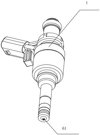
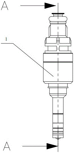
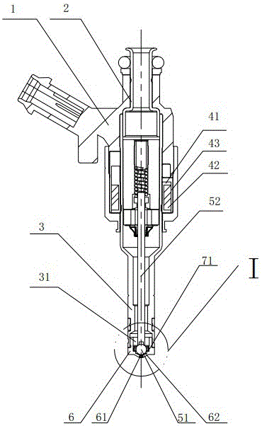
[0030] Embodiment one: by figure 1 combine figure 2 , 3 , 4, 5, 10, 11, 12, and 13, a fuel injector for an engine includes a housing 1, an oil inlet pipe 2 and an oil outlet pipe 3, the oil inlet pipe 2 communicates with the oil outlet pipe 3, and the The casing 1 is provided with a coil assembly 4, the oil outlet cavity 31 of the oil outlet pipe 3 is provided with a valve core assembly 5 and a valve cover 6, and the valve cover 6 is provided with an oil injection hole 61, and the valve core The assembly 5 includes a valve core 51 and a valve stem 52, and the valve cover 6 is provided with an oil separator 7, and the valve core 51 of the valve core assembly 5 passes through the oil separator 7 and is attached to the inner wall of the valve cover 6, An oil injection chamber 62 is formed between the valve core 51 , the oil separator 7 and the valve cover 6 , and the oil separator 7 is provided with a communication groove 71 for communicating the oil outlet chamber 31 with the...

Embodiment 2

[0034]Embodiment 2: The oil inlet pipe in Embodiment 1 is directly connected with the oil outlet pipe. In Embodiment 2, the oil inlet pipe 2 and the oil outlet pipe 3 shown in 6, 7, 8, 9, 10, and 11 can be used by adjusting The sleeve 8 is connected, and the adjustment sleeve 8 is connected with the valve core assembly 5. The valve rod 52 on the valve core assembly 5 is provided with an oil through hole 521 for communicating with the oil outlet chamber 31. The fuel oil passes through the oil inlet pipe 2, the adjustment sleeve 8, The oil through hole 521 on the valve core assembly 5 flows into the oil outlet chamber. In the first embodiment, there is a step inside the valve cover. In the second embodiment, the oil separator is directly placed in the groove of the valve cover, and the valve core is sealed with the conical surface of the valve cover. The injection from the communication groove is injected into the fuel injection chamber, and then injected into the engine to real...


PUM


Abstract

The invention discloses an injection nozzle of an engine and solves the problems that existing injection nozzles are not high in injection speed and poor in injection quality. The injection nozzle comprises a case, an oil inlet pipe and an oil outlet pipe, wherein a coil assembly is arranged in the case, a spool assembly and a bonnet are disposed in an oil outlet cavity of the oil outlet pipe, an oil injection hole is formed in the bonnet, the spool assembly comprises a spool and a valve rod, an oil baffle is arranged in the bonnet, an oil injection cavity is formed among the spool, the oil baffle and the bonnet, and a communicating groove for communicating the oil outlet cavity with the oil injection cavity is formed in the oil baffle. According to the injection nozzle, the oil baffle and the communicating groove are arranged, the injection nozzle can respond quickly for injection when the spool assembly is lifted due to the design of the communicating groove, fuel oil is atomized to a certain extent when passing through the communicating groove before ejected from the oil injection hole due to arrangement of the oil baffle and the communicating groove, and the fuel oil is atomized twice, so that the fuel oil is atomized thoroughly.

Description

technical field [0001] The invention relates to the field of an engine fuel injector, in particular to an engine fuel injector. Background technique [0002] The fuel injector itself is a normally closed valve (normally closed valve means that the valve is always closed when there is no input control signal), and the opening and closing of the valve is controlled by a valve needle moving up and down. When the ECU issues a fuel injection command, its voltage signal will cause current to flow through the coil in the fuel injector, generating a magnetic field to attract the valve needle, allowing the valve to open so that fuel can be sprayed out from the fuel injection hole. The biggest advantage of injection fuel supply is that the control of fuel supply is very precise, so that the engine can have the correct air-fuel ratio in any state, not only to keep the engine running smoothly, but also the exhaust gas can meet the environmental protection regulations. [0003] As one o...

Claims


Application Information

Patent Timeline
Patent Type & Authority Patents(China)
IPC IPC(8): F02M61/04F02M61/16
Inventor 赵典秋
Owner WENZHOU BATON ELECTRONICS TECH
Why Eureka
Try Eureka