Eureka AIR delivers breakthrough ideas for toughest innovation challenges, trusted by R&D personnel around the world.

Pipeline explosion-proof device capable of automatically replacing anti-explosion sheets

An explosion-proof device and automatic replacement technology, applied in the valve operation/release device, valve device, engine components, etc., can solve the problems of time-consuming and laborious, affecting the combustion state of the industrial furnace burner, affecting the stable operation of the system, etc., to achieve fast replacement. Effect

Inactive Publication Date: 2013-11-27
WISDRI WUHAN WIS IND FURNACE
View PDF3 Cites 1 Cited by
  • Summary
  • Abstract
  • Description
  • Claims
  • Application Information

AI Technical Summary

Problems solved by technology

Disadvantages: 1. When the gas-air mixture is ignited and exploded in the pipeline, and the explosion-proof plate of the explosion-proof device is damaged, the end of the pipeline is changed from blocked to open, and the pressure of the pipeline fluctuates greatly, which affects the burner of the industrial furnace. The combustion state directly affects the stable operation of the entire system; 2. If the explosion-proof disk is replaced during the non-stop production, due to the openness of the end of the pipeline, the replacement is carried out under pressure, and the work is difficult; and there are Possibility of Gas Poisoning
3. When replacing, it is necessary to remove all the fasteners between the pipe end flange and the safety cover, which is time-consuming and laborious

Method used


Image

  • Pipeline explosion-proof device capable of automatically replacing anti-explosion sheets
  • Pipeline explosion-proof device capable of automatically replacing anti-explosion sheets
  • Pipeline explosion-proof device capable of automatically replacing anti-explosion sheets

Examples


Embodiment Construction

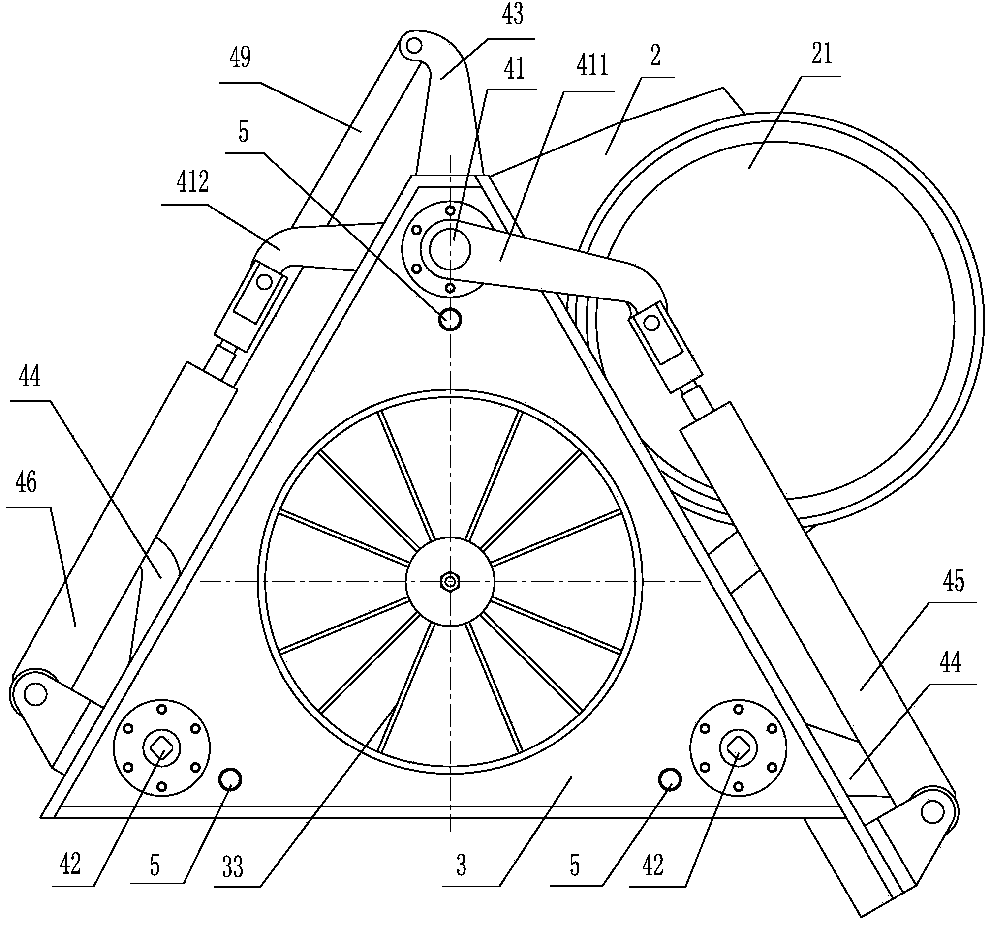
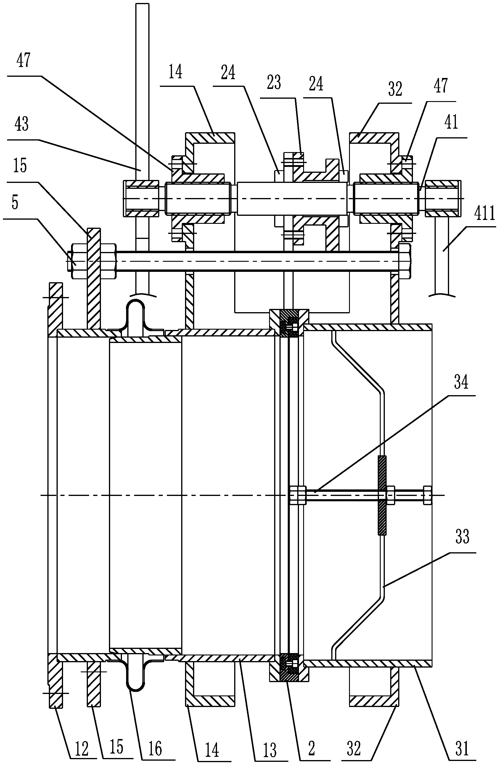
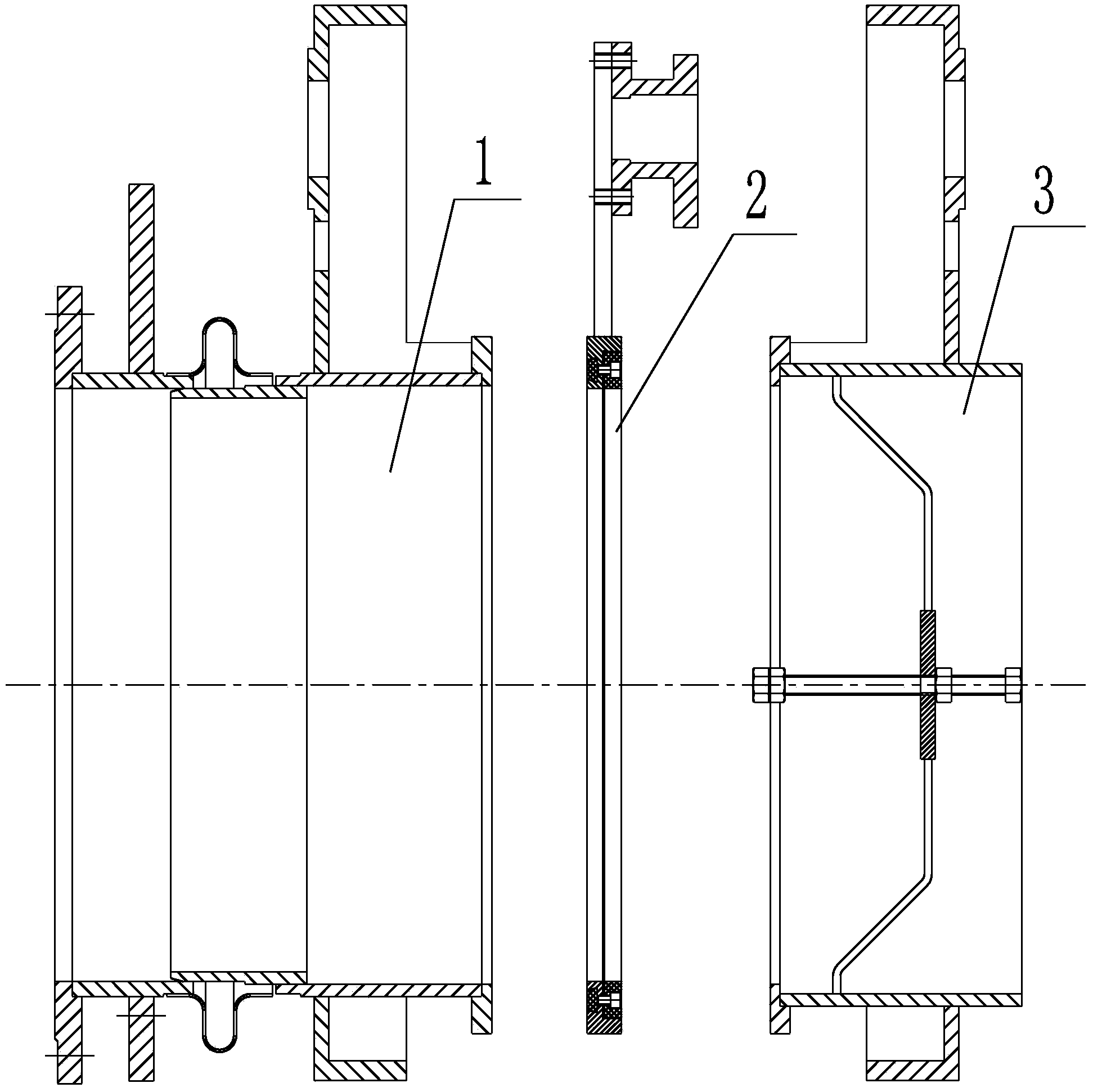
[0032] In order to understand the present invention better, below in conjunction with embodiment and accompanying drawing, the technical solution of the present invention will be further described (see Figure 1-Figure 7 ).

[0033] Such as Figure 1 to Figure 7 As shown, a pipeline explosion-proof device that can automatically replace the explosion-proof disc, which includes a flange connection device 1, a double-hole gate 2, a fixing device 3 and a linkage device 4; the flange connection device 1, the double-hole gate 2 and the fixing The device 3 is connected through the linkage device 4, and the double-hole gate 2 is tightly clamped between the flange connection device 1 and the fixing device 3;

[0034] The flange connection device 1 includes a connecting flange 12 and a connecting pipe 13, the connecting flange 12 and the connecting pipe 13 are fixedly connected as one, and the connecting flange 12 is fixedly connected with the end of the pipeline; the connecting pipe 1...


PUM


Abstract

The invention relates to a pipeline explosion-proof device capable of automatically replacing anti-explosion sheets. The pipeline explosion-proof device is characterized by comprising a flange connection device, a double-hole flashboard, a fixing device and a linkage device, wherein the flange connection device, the double-hole flashboard and the fixing device are connected through the linkage device, and the double-hole flashboard is clamped between the flange connection device and the fixing device in a sealing mode. The linkage device comprises a tightness degree driving device and a swinging driving device, wherein the tightness degree driving device enables the sealed clamping state of the flange connection device and the double-hole flashboard clamped by the fixing device to transmit to a release state, and the swinging driving device is used for driving the double-hole flashboard to swing so as to finish automatic replacing of the anti-explosion sheets. The pipeline explosion-proof device can automatically replace the anti-explosion sheets, is fast and convenient to replace, shortens replacing from tens of minutes to several seconds, saves time and effort, enables the whole system to operate stably due to the fact that the replacing is fast and convenient and cannot influence combustion state of a nozzle of an industrial furnace and can not cause carbon monoxide poisoning due to automatic anti-explosion sheet replacing.

Description

technical field [0001] The invention relates to an explosion-proof device for air and gas pipelines of industrial furnaces, in particular to a pipeline explosion-proof device that can automatically replace explosion-proof sheets. Background technique [0002] For industrial furnaces that use gas as fuel, an explosion-proof device should be installed on the air pipe in front of the furnace. In order to ensure that the possible gas-air mixture is ignited and exploded in the pipeline and limit its generated pressure within the range of 100-450kPa, the pressure relief area per unit pipeline volume should not be less than 0.06-0.01m2 / m3. [0003] Existing explosion-proof devices for industrial furnace pipelines that use coal gas as fuel are composed of pipe end flanges, flange gaskets, explosion-proof discs, safety covers and fasteners. Disadvantages: 1. When the gas-air mixture is ignited and exploded in the pipeline, and the explosion-proof plate of the explosion-proof device ...

Claims


Application Information

Patent Timeline
IPC IPC(8): F16K31/12F16K31/52F16K17/40
Inventor 李飞
Owner WISDRI WUHAN WIS IND FURNACE
Why Eureka
Eureka Blog
Learn More