Ultrathin Mini-LED backlight source capable of emitting light uniformly

A technology with uniform light and mini-led, applied in optics, nonlinear optics, instruments, etc., can solve the problems of inability to quickly disassemble and install, low efficiency, uneven lighting, etc.

Inactive Publication Date: 2022-03-22
江苏庆亚电子科技有限公司
View PDF0 Cites 0 Cited by
  • Summary
  • Abstract
  • Description
  • Claims
  • Application Information

AI Technical Summary

Problems solved by technology

[0004] In order to solve the above-mentioned technical problems, a method is provided. This technical solution solves the problem that the Mini-LED backlight inside the existing large-scale display screen in the above-mentioned background technology is worn out during long-term use, and when the light irradiation is uneven, Usually to replace the Mini-LED backlight, the irradiation distance of the Mini-LED backlight cannot be adjusted, resulting in unclear imaging of the LC display, and increasing the waste of the Mini-LED backlight, and when the light is refracted through the reflector, usually the refraction The plate is fixed at the front of the Mini-LED backlight, and the size of the refraction plate cannot be adjusted to adjust the refraction range of the Mini-LED backlight light, resulting in uneven light, and when the Mini-LED backlight shines on the refraction plate for a long time, the refraction The plate generates a high temperature, and the refraction of the surface of the refraction plate is weakened after long-term use, so it needs to be disassembled and replaced. The existing refraction plate disassembly mechanism is relatively cumbersome and cannot be disassembled and installed quickly, resulting in low efficiency and increased work intensity. The problem

Method used


Image

  • Ultrathin Mini-LED backlight source capable of emitting light uniformly
  • Ultrathin Mini-LED backlight source capable of emitting light uniformly
  • Ultrathin Mini-LED backlight source capable of emitting light uniformly

Examples


Embodiment Construction

[0030] The following will clearly and completely describe the technical solutions in the embodiments of the present invention with reference to the accompanying drawings in the embodiments of the present invention. Obviously, the described embodiments are only some, not all, embodiments of the present invention. Based on the embodiments of the present invention, all other embodiments obtained by persons of ordinary skill in the art without making creative efforts belong to the protection scope of the present invention.

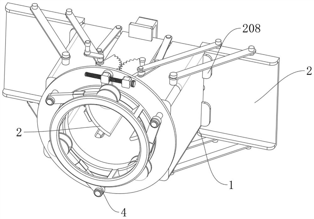
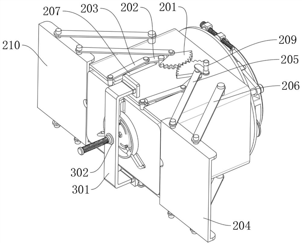
[0031] refer to figure 1 and figure 2 As shown, an ultra-thin Mini-LED backlight with uniform luminescence includes a housing 1, a spacing adjustment mechanism 2 is provided at the rear end of the housing 1, an aperture adjustment mechanism 3 is provided at the front end of the spacing adjustment mechanism 2, and an aperture adjustment mechanism 3 is provided at the front end of the housing 1. There is a replacement mechanism 4, and the spacing adjustment me...


PUM


Abstract

A replacement mechanism comprises an arc hollowed-out mounting disc, positioning rods are evenly and fixedly connected into the diameter of the arc hollowed-out mounting disc, power rotating rods are rotationally connected to the outer surfaces of the front ends of the positioning rods, and positioning sliding sleeves are slidably connected to the middle ends of the power rotating rods; positioning frames are rotationally connected to the upper and lower ends of the positioning sliding sleeve, clamping plates are fixedly connected to one ends of the power rotating rods, first square blocks are rotationally connected to the upper ends of the positioning frames, and bolt rods are in threaded connection to the middle ends of the first square blocks. The rear end of the second square block is fixedly connected to the front end face of the arc hollowed-out mounting disc. A concave lens is placed in the middle of a positioning frame, then a bolt rod drives a first square block to move leftwards, the first square block drives the positioning frame to rotate, the positioning frame drives a positioning sliding sleeve to rotate and move, and the positioning sliding sleeve slides on the outer surface of a power rotating rod and drives one end of the power rotating rod to move inwards; meanwhile, the clamping plate is driven to move inwards, and the edge of the concave lens is clamped through a hollowed-out groove formed in the middle of the clamping plate.

Description

technical field [0001] The invention relates to the field of Mini-LED backlight sources, in particular to an ultra-thin Mini-LED backlight source with uniform light emission. Background technique [0002] With the rapid development of Mini LED display technology, Mini LED display products have begun to be used in ultra-large-screen high-definition displays, such as monitoring and command, high-definition broadcasting, high-end theaters, medical diagnosis, advertising display, conferences and exhibitions, office displays, virtual reality and other commercial fields. The Mini-LED backlight is easy to wear out after long-term use, and it is impossible to adjust the irradiation range of the Mini-LED backlight, LCD display and Mini-LED backlight to extend the life cycle of the Mini-LED backlight. [0003] The Mini-LED backlight inside the existing large-scale display is worn out during long-term use, and when the light irradiation is uneven, the Mini-LED backlight is usually repl...

Claims


Application Information

Patent Timeline
Patent Type & Authority Applications(China)
IPC IPC(8): G02F1/13357
CPCG02F1/133603G02F1/133608G02F1/133607G02F1/133605G02F1/133611
Inventor 吴楠沈庆成
Owner 江苏庆亚电子科技有限公司
Why Eureka
Try Eureka