Conduit single arm sliding/guiding support assembly

A technology for supporting components and pipe sheets, which is applied in the direction of pipe supports, pipes/pipe joints/fittings, mechanical equipment, etc., can solve the problems of distance limitation, large space occupation, tearing and damage of pipe insulation layer, etc., to reduce friction , the effect of taking up less space

Active Publication Date: 2008-02-20
SHANGHAI NUCLEAR ENG RES & DESIGN INST CO LTD
View PDF0 Cites 31 Cited by
  • Summary
  • Abstract
  • Description
  • Claims
  • Application Information

AI Technical Summary

Problems solved by technology

[0004] The pipeline sliding and guiding supports shown in Figures 14 and 15 all have the following disadvantages: (1) they all require at least a gantry frame structure containing the pipeline, which takes up a lot of space and easily affects other pipelines around the supported pipeline and their Arrangement of supports; not only that, this frame structure also has a certain limit on the distance between the supported pipe and the root of the support. If the above distance is too close, the sliding or guiding support cannot be designed for the pipe here.
(2) Regardless of sliding or guiding, the above two supports allow the pipe to move along its axial line, but the pipe must overcome the friction between the U-shaped plate and the bottom plate or the friction between the U-shaped plate and the baffle to achieve its Axial displacement; in actual use, due to excessive friction, it sometimes happens that the pipeline cannot achieve sufficient axial displacement, and some even cause the insulation layer of the pipeline to be torn and damaged
(3) The pipe part is a double U-shaped plate, and most of them are double pipe clamps, which is not only bulky, but also affects the installation and effect of pipe insulation
(4) For pipes that are far away from columns, walls, beams, and floors, that is, so-called suspended pipes, the sliding and guiding restraint methods of the above-mentioned gantry frame structure are not easy to implement, and if they must be set, it will eventually lead to complicated and very occupied Space steel frame
In addition, the tie rod supports shown in Figures 16 and 17 only allow small linear displacements in two directions other than the constraint direction, because even if the two ends of the tie rods are connected by ball joints, a certain amount of linear displacement can be satisfied, but if the line If the displacement is too large, the constraint mode of the tie rod on the pipeline will change from one-way to two-way, or even three-way, and the resulting additional influence on the pipeline must be obtained by modifying and recalculating the original pipeline calculation model

Method used


Image

  • Conduit single arm sliding/guiding support assembly
  • Conduit single arm sliding/guiding support assembly
  • Conduit single arm sliding/guiding support assembly

Examples


Embodiment Construction

[0029] The sliding / guiding support assembly of the present invention will be further described below with reference to the drawings and embodiments.

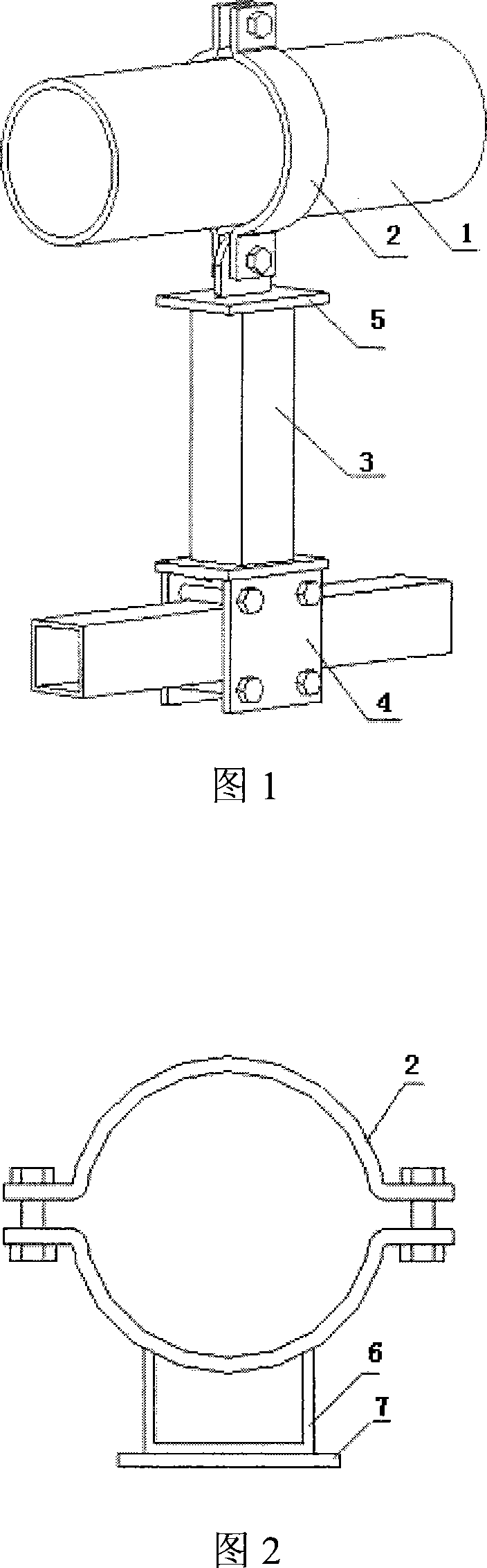
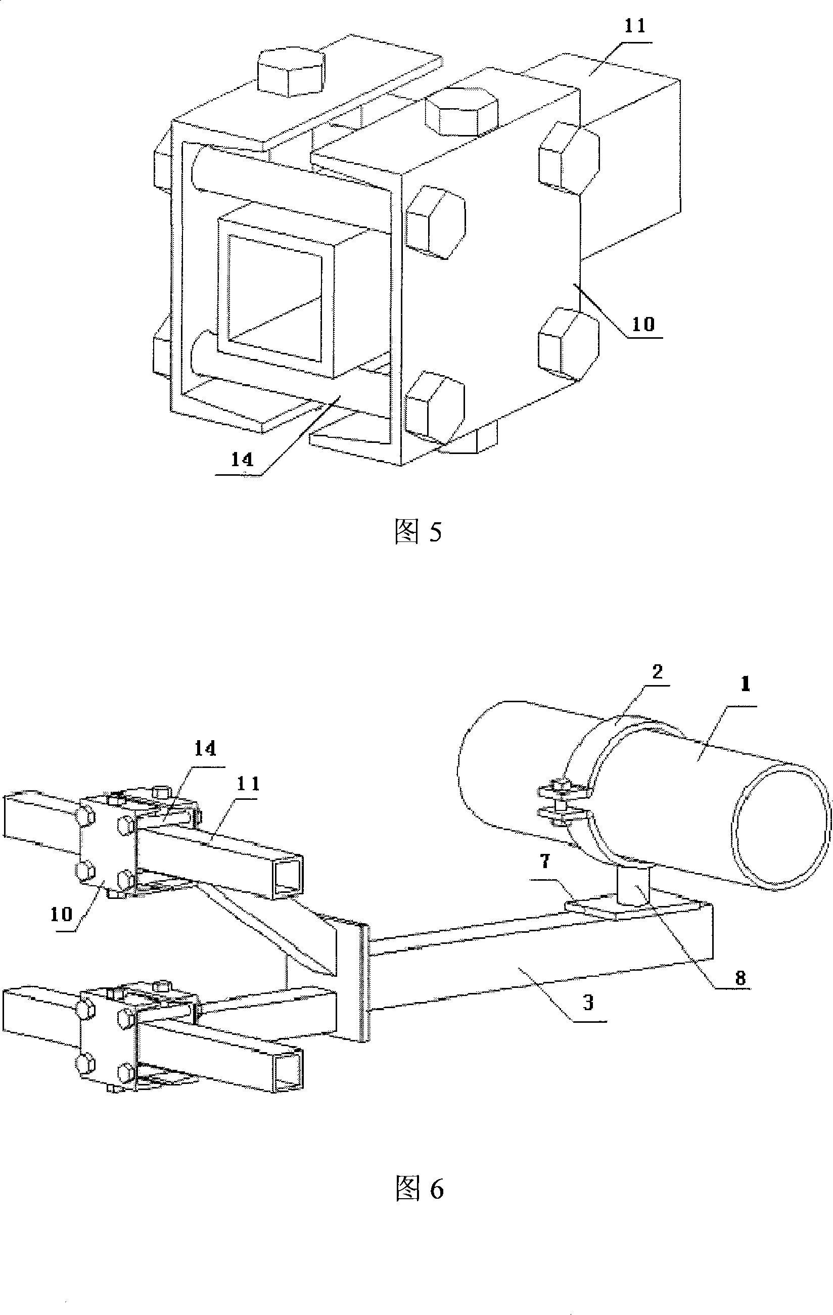
[0030] As shown in Figure 1, a pipeline single-arm sliding / guiding support assembly includes a pipe clamp 2 for clamping the supported pipeline, wherein it also includes a single-arm structural beam 3, and the root of one end of the single-arm structural beam 3 It is fixedly connected with the monorail sliding constraint assembly 4 so as to fix the single-arm structural beam 3 on structures such as columns, walls or floors, and the pipe clamp 2 is connected with the other end of the single-arm structural beam 3 through the pipe connection assembly 5 to realize the pipeline Required sliding / guiding constraints.

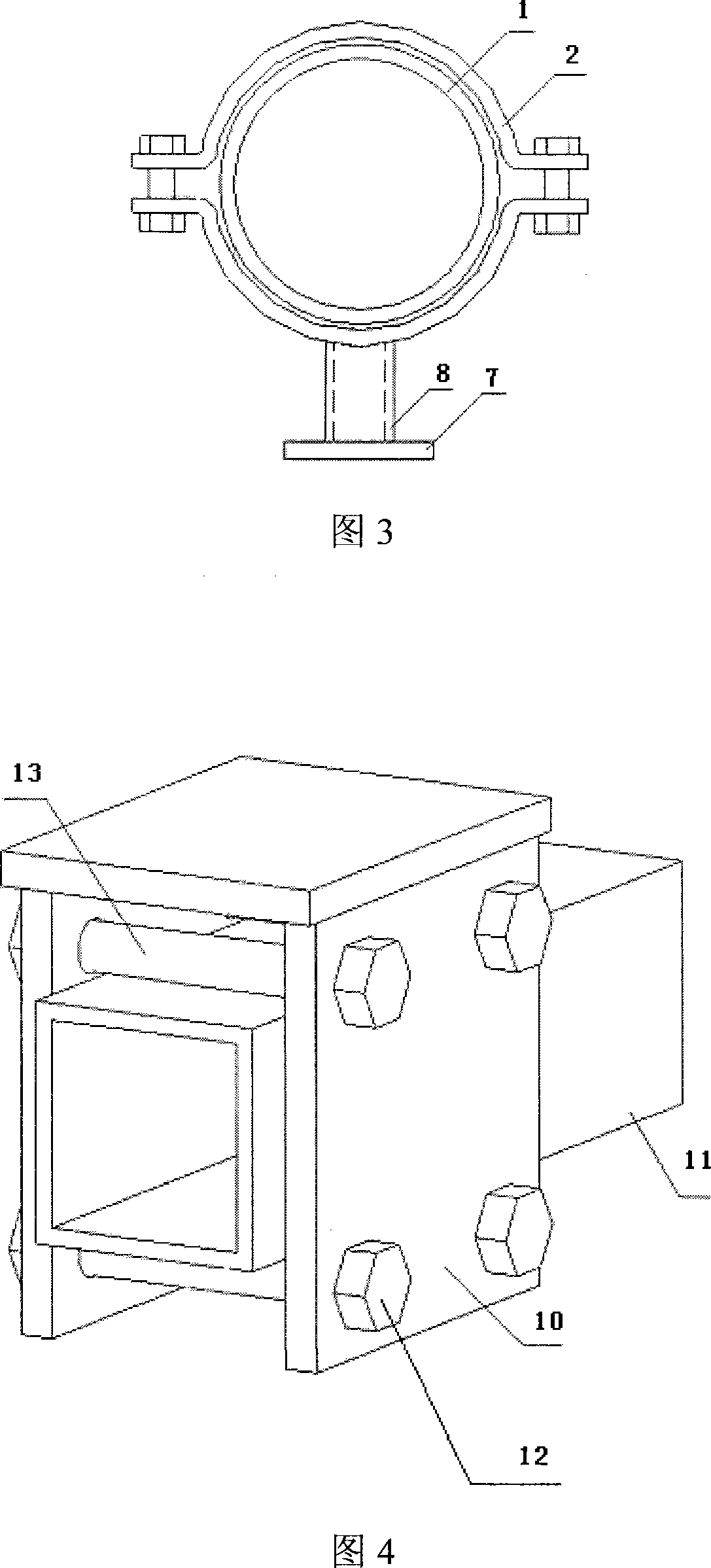
[0031] As shown in Figures 2, 3, 4, 6, 7 and 8, the pipe connection assembly 5 is composed of a U-shaped plate 6 or a support pipe 8 and a bottom plate 7; the pipe connection assembly 5 can also be made of a U-shaped pla...


PUM


Abstract

The invention belongs to the pipe support field and specifically discloses a pipe single-arm sliding/guiding support component, which includes a pipe clip to clip the pipe and a single-arm structural beam; one end of the single-arm structural beam is fixedly connected with a single-rail sliding limit component so that the single-arm structural beam can be fixed on a post, a wall or a floor, etc.; the pipe clip is connected with the other end of the single-arm structural beam by a pipe connecting component to realize the sliding/guiding limitation required by the pipe. The support component provided by the invention occupies smaller area, and is convenient to arrange, and is not limited by the distance from the pipe to the support root, which reduces the unfavorable influence on the pipe caused by the friction between the support component and the unfavorable influence on the heat insulation of the pipe caused by the support.

Description

technical field [0001] The invention belongs to a pipeline support device, in particular to a sliding / guiding support assembly. Background technique [0002] In the piping design of the nuclear process system of a nuclear power plant, the sliding support of the pipe constrains the reciprocating line displacement of the pipe in any direction perpendicular to the axial direction of the pipe; the guiding support of the pipe restricts the displacement of the pipe in any two orthogonal directions perpendicular to the axial direction of the pipe reciprocating line displacement. For the above two restraint methods, the commonly used support forms are shown in Figures 14 and 15. Their main features are: (1) The pipe part is double pipe clamp (heat pipe) or single pipe clamp (cold pipe), and the pipe clamp is divided into two types without reinforcement plate or with reinforcement plate; (2) The connection part is long U-shaped plate (heat pipe) or short U-shaped plate (cold pipe);...

Claims


Application Information

Patent Timeline
Patent Type & Authority Applications(China)
IPC IPC(8): F16L3/18
Inventor 梁兵兵李岗王勇王高阳
Owner SHANGHAI NUCLEAR ENG RES & DESIGN INST CO LTD
Why Eureka
Try Eureka