Telephone remote light controller

A controller and telephone technology, which is applied in the fields of electric light source, telephone communication, energy-saving control technology, etc., can solve the problems of long construction period, high technical difficulty, waste of electricity, etc., and achieve the effects of low cost, flexible control and simple maintenance.

Inactive Publication Date: 2010-02-24
WUHAN RUIXIANG ADVERTISEMENT
View PDF3 Cites 0 Cited by
  • Summary
  • Abstract
  • Description
  • Claims
  • Application Information

AI Technical Summary

Problems solved by technology

These two methods cannot achieve effective control for the time period and date that do not need lighting, and will cause a lot of waste of electricity. Therefore, they are often not fully adopted by urban lighting control, and can only be used as a means of lighting and turning off lights. Auxiliary means, many buildings in the process of lighting are required to switch on and off the lights manually from door to door during the period or date when the lights need to be turned on
[0004] Another method of lighting control is to use the wireless public network GSM or GPRS remote centralized control method. This method is a relatively advanced remote lighting control technology today. Using GSM or GPRS remote centralized control requires a large initial investment. It is understood that Only a set of equipment in the monitoring center is as high as more than 2 million yuan, and each terminal equipment is also more than 10,000 yuan. There is also the construction of the base station, and the construction period is also very long
In the actual use process, the accessories are in short supply and the technology is difficult. If the control terminal fails, it is indeed a difficult problem in our actual work to quickly troubleshoot the fault.

Method used


Image

  • Telephone remote light controller

Examples


Embodiment Construction

[0010] The detailed description and technical content of the present invention are described below with the drawings, but the drawings are only for reference and description, and are not intended to limit the present invention.

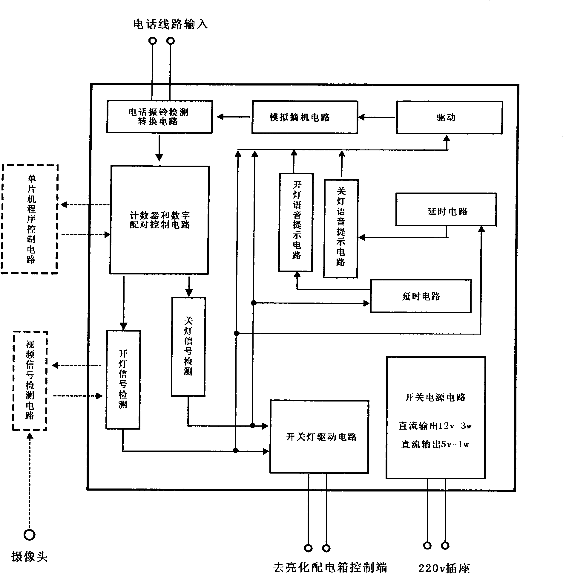
[0011] see figure 1 As shown, the present invention provides a telephone remote lighting controller, wherein the telephone remote lighting controller includes a telephone line input terminal, a telephone ringing detection conversion circuit, a counter and a digital pairing control circuit, and a light on / off signal detection circuit, on / off light drive circuit. When a telephone is dialed in, the telephone ringing detection conversion circuit receives the telephone ringing signal from the input terminal of the telephone line, and converts the pulse into the counter and the digital pairing control circuit, and when the telephone pulse arrives at the counter and the digital pairing control circuit is set When the number of pulses is fixed, the on / off li...


PUM


Abstract

The invention discloses a telephone remote light controller, which comprises a telephone line input end, a telephone ringing detection and conversion module, a counter, a digital pairing control circuit, a lamp turning on/off signal detection circuit and a lamp turning on/off drive circuit, wherein the telephone ringing detection and conversion module receives a telephone ringing signal from the telephone line input end, converts the telephone ringing signal into a pulse and sends the pulse to the counter and the digital pairing control circuit; and when the telephone pulse reaches a pulse frequency set by the counter and the digital pairing control circuit, the lamp turning on/off signal detection circuit respectively drives the lamp turning on/off drive circuit in a preset mode. The telephone remote light controller has the function of remote light control at any position and in any area, and is particularly suitable for the remote control of the outdoor lighting of medium and large-sized buildings and the lighting of billboards.

Description

technical field [0001] The invention relates to a remote controller, in particular to a telephone remote lighting controller. Background technique [0002] With the development of reform and opening up, urban lighting has gradually become a scale. Strolling through the streets, the neon lights are flashing and colorful, presenting a beautiful scene of harmony and prosperity. [0003] In order to save energy, reduce unnecessary waste, and strengthen the management of urban lighting, time program controllers and photosensitive controllers are currently mainly used to control urban lighting. These two methods cannot achieve effective control for the time period and date that do not need lighting, and will cause a lot of waste of electricity. Therefore, they are often not fully adopted by urban lighting control, and can only be used as a means of lighting and turning off lights. Auxiliary means, many buildings in the process of lighting are required to switch on and off the li...

Claims


Application Information

Patent Timeline
Patent Type & Authority Applications(China)
IPC IPC(8): H05B37/02H04M11/00H04Q9/00
CPCY02B20/42Y02B20/40
Inventor 周齐宇
Owner WUHAN RUIXIANG ADVERTISEMENT
Why Eureka
Try Eureka