
A profile and non-profile connection structure

A connection structure, non-profile technology, applied in the direction of slender components, building components, etc., can solve the problems of high appearance requirements, high connection method requirements, low positioning accuracy, etc., to achieve excellent appearance, firm and reliable connection methods, and easy installation high precision effect

Active Publication Date: 2016-08-10
陕西海泰电子有限责任公司
View PDF6 Cites 0 Cited by
  • Summary
  • Abstract
  • Description
  • Claims
  • Application Information

AI Technical Summary

Problems solved by technology

For cabinet products, the profiles are mainly used for frame structures, and the requirements for the connection between the profiles and the frame joints are relatively high. The traditional clamping and gluing methods cannot meet the large load-bearing requirements, while the welding and threaded forms are The positioning accuracy is relatively low. In addition, the appearance requirements for cabinet products are getting higher and higher

Method used


Image

  • A profile and non-profile connection structure

Examples


specific Embodiment approach

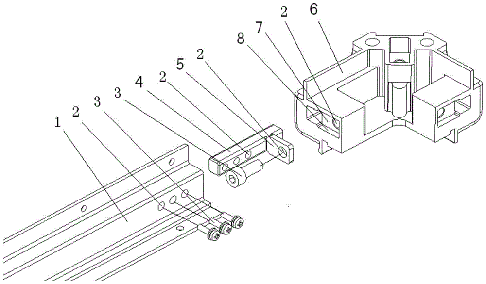
[0019] Such as figure 1 As shown, the profile 1 is a hollow cavity, and the side wall of the profile end is processed with three through holes 2; the pin shaft 4 is processed with three corresponding through holes 2, and the connecting arm 5 has a through hole 2; figure 1 The non-profile 6 used in is a corner block with a positioning groove 8 on it. The mounting surface of the positioning groove 8 has a fixing groove 7 corresponding to the connecting arm 5 and a through hole 2. The through hole 2 is arranged in the fixing groove 7 Inside. During installation, one end of the front part of the pin shaft 4 is inserted into the inner cavity of the terminal part of the profile 1, the through hole 2 on the front part of the pin shaft 4 corresponds to the through hole 2 on the inner cavity of the terminal part of the profile 1, and the screw 3 passes through the end of the profile 1 The through hole 2 on the inner cavity of the connection part is connected with the through hole 2 on...


PUM


Abstract

The invention provides a connecting structure of a profile and a non-profile. The connecting structure comprises a profile end connecting portion, a pin shaft and a non-profile end connecting portion. The side face of the front portion of the pin shaft is provided with a through hole, the side face of the rear portion of the pin shaft is vertically provided with a connecting arm, the connecting arm is provided with a through hole in the axial direction of the pin shaft, the shape and the size of an inner cavity of the profile end connecting portion are matched with those of the front portion of the pin shaft, the side wall of the profile end connecting portion is provided with a through hole, and the through hole is matched with the through hole in the front portion of the pin shaft. The non-profile end connecting portion is provided with a positioning groove matched with the rear portion of the pin shaft, a through hole is formed in the positioning groove, the through hole is matched with the through hole in the connecting arm, the front portion of the pin shaft is inserted into the inner cavity of the profile end connecting portion, the rear portion of the pin shaft is inserted into the positioning groove of the non-profile end connecting portion, and the front portion and the rear portion of the pin shaft are fastened and installed through the through holes by means of connecting elements. The connecting structure has the advantages that the profile and the non-profile can be tensioned in the installation direction so that joint seams are tight, installation is firm and reliable in the method, and appearance of products is not influenced.

Description

technical field [0001] The invention relates to a structural connection of cabinet products mainly used in the fields of electronics, communication and machinery, in particular to an internal connection structure of profiles and non-profiles of cabinet products. Background technique [0002] Profiles have been widely used in the fields of electronics, communication and machinery with the advantages of low cost, high strength and convenient processing. At present, the connection methods between profiles and non-profiles are mainly in four forms: clamping, welding, gluing and threading. For cabinet products, the profiles are mainly used for frame structures, and the requirements for the connection between the profiles and the frame joints are relatively high. The traditional clamping and gluing methods cannot meet the large load-bearing requirements, while the welding and threaded forms are The positioning accuracy is relatively low. In addition, the requirements for the appe...

Claims


Application Information

Patent Timeline
Patent Type & Authority Patents(China)
IPC IPC(8): F16S3/06
Inventor 郭恩全李成张鑫
Owner 陕西海泰电子有限责任公司
Learn More