A wire receiving jig

A technology of wires and jigs, which is applied in the manufacture of cables/conductors, devices with bendable leads, electrical components, etc. It can solve problems that affect the collection speed, machine damage, and the collection rack cannot continue to rotate and collect, so as to achieve fast collection. stable effect

Active Publication Date: 2017-02-01
KUSN MAIZHI FIXTURE TECH
View PDF5 Cites 0 Cited by
  • Summary
  • Abstract
  • Description
  • Claims
  • Application Information

AI Technical Summary

Problems solved by technology

[0003] In order to solve the problem that in the prior art, the wires are placed in the stacker and then rotated to collect the wires, the wires are not positioned during the rotation process and may be thrown out of the stacker, causing the stacker to fail to continue to rotate and collect, affecting the quality of the collection. speed, it is also very easy to cause damage to the machine

Method used


Image

  • A wire receiving jig

Examples


Embodiment Construction

[0010] The present invention will be further described below in conjunction with the accompanying drawings.

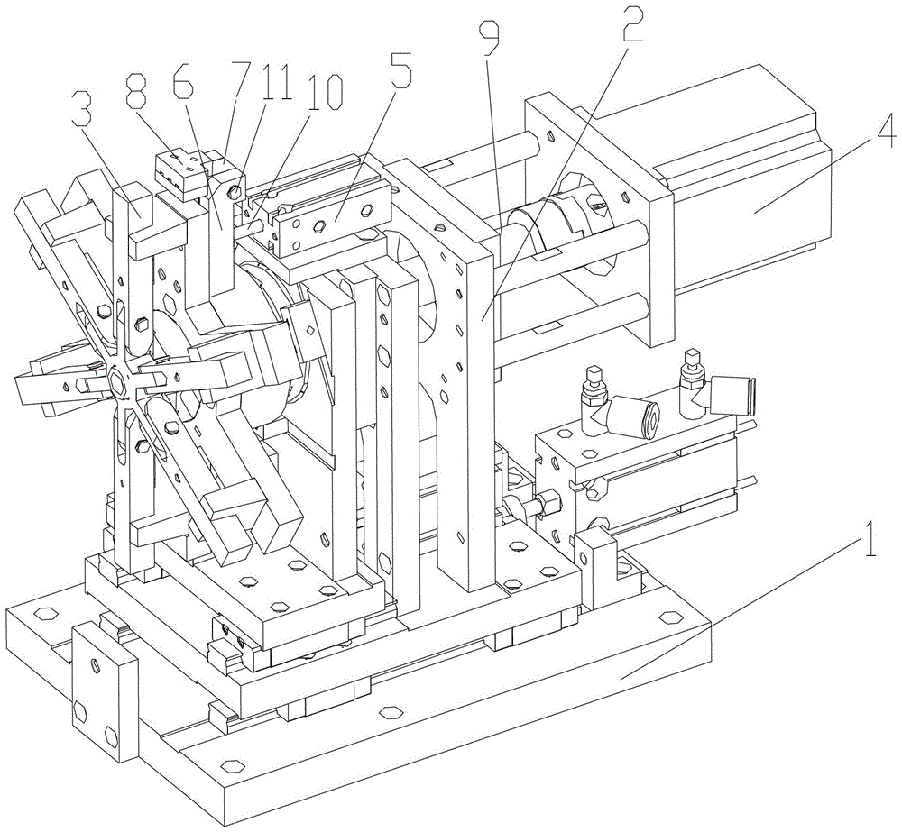
[0011] Such as figure 1 As shown, a wire receiving fixture includes a base 1, a connecting plate 2, a receiving rack 3, a motor 4, a cylinder 5, a fixed seat 6, a rotating arm 7 and a pressing block 8, and a connecting plate is arranged above the base 1 2. A receiving frame 3 is arranged in front of the connecting plate 2, the output shaft 9 of the motor 1 passes through the connecting plate 2 and is connected to the center of the receiving frame 3, and a cylinder 5 is arranged on the top of the connecting plate 2, and the receiving frame 3 is provided with a fixed seat 6, the top of the rotating arm 7 is flexibly connected in the fixed seat 6 through a pin shaft 11, and a pressure block 8 is connected to the front end of the top of the rotating arm 7, and the rear end of the rotating arm 7 is connected to the cylinder of the cylinder 5 Rod 10 is connected. During de...


PUM


Abstract

The invention discloses a wire collection jig. The wire collection jig comprises a base and a connection plate, and the connection plate is arranged above the base. The wire collection jig is characterized in that a collection frame is arranged before the connection plate; a motor output shaft penetrates through the connection plate and is connected with the center of the collection frame; an air cylinder is arranged on the top of the connection plate; a fixing seat is arranged on the collection frame; the top of a rotating arm is movably connected to the interior of the fixing seat through a pin shaft; a pressing block is connected to the front end of the top of the rotating arm; the rear end of the rotating arm is connected with an air cylinder rod of the air cylinder. The wire collection jig solves the problem that when wires are placed in the collection frame, and the collection frame is rotated to collect the wires, the wires will be possibly tossed out of the collection frame because of being not positioned in the rotating process, and the collection frame can not continue rotating to collect the wires; meanwhile, the tossed wires are very difficult to untangle again because of being wound together. The wire collection jig is simple in structure, convenient to use, and capable of positioning the wires to the interior of the collection frame and ensuing that the wires will not be tossed out of the collecting frame.

Description

technical field [0001] The invention relates to a material receiving jig, in particular to a wire receiving jig. Background technique [0002] The wires on the connector often need crimping terminals. The process of crimping the wires is: cut off the insulation at the end of the wire, heat and peel off the insulation at the end, then install the terminal and the wire, and then crimp Wires and terminals, and finally collect the wires with crimped terminals. During the wire collection process, if the wire is directly placed in the stacker and then rotated to collect the wire, the wire may not be positioned during the rotation and may be thrown out of the stacker, causing the stacker to fail to continue to rotate and collect. It affects the speed of collection, and it is also very easy to cause damage to the machine. At the same time, if the wires thrown out are entangled together, it is also very difficult to reorganize the wires, and it takes a lot of time. Contents of th...

Claims


Application Information

Patent Timeline
Patent Type & Authority Patents(China)
IPC IPC(8): H01B13/00H01R13/72
Inventor 黄锦章
Owner KUSN MAIZHI FIXTURE TECH
Why Eureka
Try Eureka