Vehicle pneumatic tires

一种车辆、轮胎的技术,应用在充气轮胎的增强层、重型轮胎、重型车辆等方向,能够解决有限带束耐用性等问题,达到减小滚动阻力、提高滚动阻力的效果

Active Publication Date: 2013-11-27
CONTINENTAL REIFEN DEUTSCHLAND GMBH
View PDF6 Cites 5 Cited by
  • Summary
  • Abstract
  • Description
  • Claims
  • Application Information

AI Technical Summary

Problems solved by technology

In US 5,772,810A it is proposed to connect the working ply outside the zero degree ply in order to overcome the problems associated with these belt ply designs having inextensible strength members which relate to the Limited belt durability due to movement of the belt edge of the member

Method used


Image

  • Vehicle pneumatic tires
  • Vehicle pneumatic tires
  • Vehicle pneumatic tires

Examples


Embodiment Construction

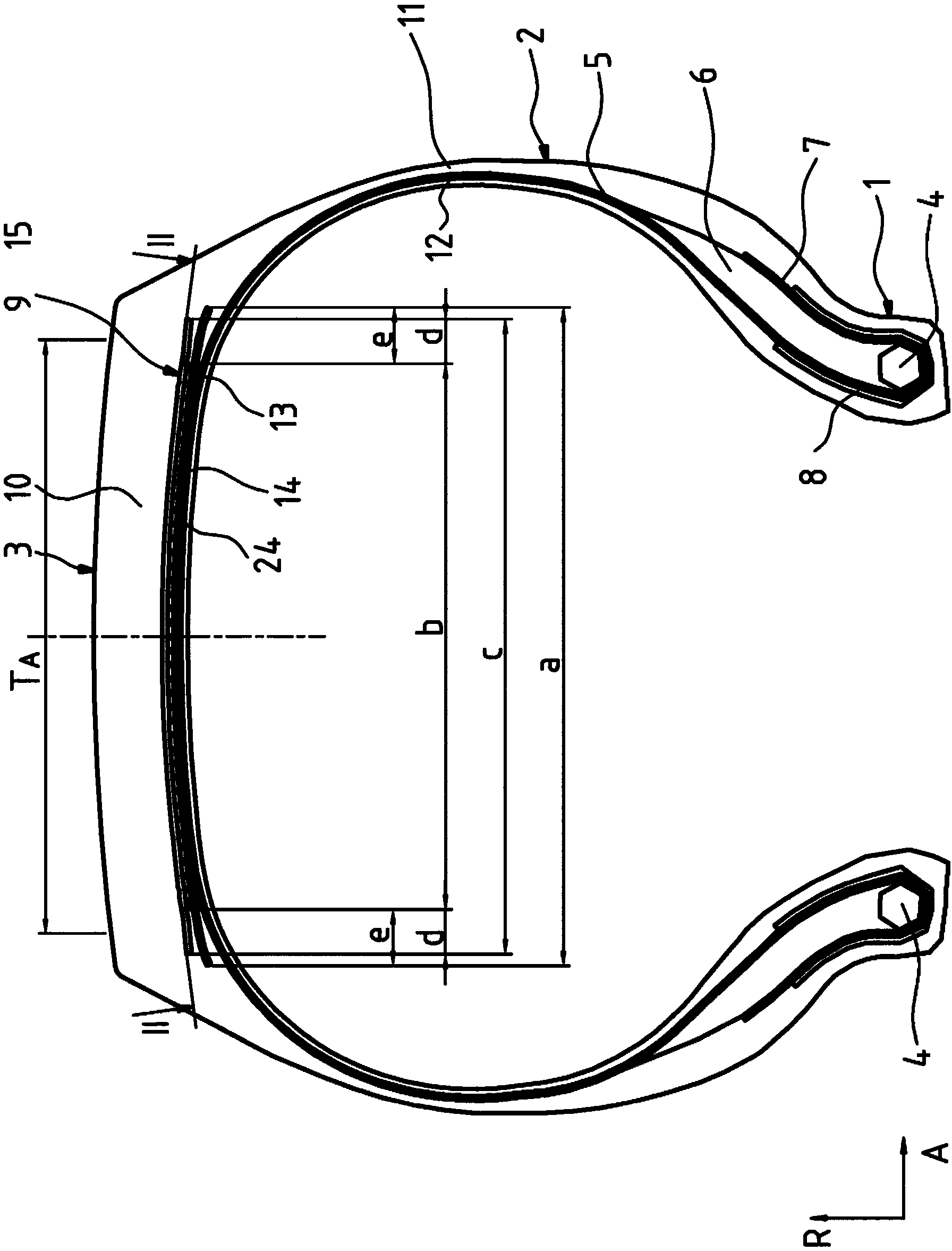
[0054] figure 1 and figure 2 A pneumatic tire of radial design for a utility vehicle is shown, having two side walls 2 extending in the direction R of the vehicle tire, and an axially formed between them A crown area3. These side walls are each formed on their radially inwardly directed extension ends with a bead region 1 in which a bead core 4 of known design is formed, the bead core It has a high tensile strength in the circumferential direction U and extends over the circumference of the tire in this circumferential direction. The bead cores 4 are formed by winding in a known manner steel wires extending in the circumferential direction U of the pneumatic vehicle tire and embedded in rubber. A tip 6 having a triangular cross section is formed on the bead core 4 by a hard rubber material. The pneumatic vehicle tire is formed with a carcass 5 extending outward in the radial direction R of the pneumatic vehicle tire from a bead core 4 formed in the left bead region 1 of ...


PUM


Abstract

The invention relates to vehicle pneumatic tires for utility vehicles comprising a carcass (5), a belt (9) and a profiled tread (10), wherein the belt (9) consists of three belt layers (13, 14, 15), wherein the radial inner (13) and the radial outer (15) belt layers are working layers having reinforcements (23, 25) made of steel, and wherein the belt layer (14) arranged between said two working layers (13, 15) is a belt layer designed as a zero degree layer, characterized in that the two working layers (13, 15) are wider than the belt layer (14) designed as a zero degree layer and are coupled to each other in the axial direction outside of the belt layer (14) at a length p of p > 0mm so that the distance s of the reinforcements (23) of the one working layer (13) to the reinforcements (25) of the other working layer (15) is designed to be s<1.5mm.

Description

technical field [0001] The present invention relates to a pneumatic vehicle tire, particularly for utility vehicles, having a carcass; having a belt formed radially outside the carcass; and having a belt formed radially outside the belt A shaped tread on a belt, wherein the belt is formed of at least three belt plies arranged one above the other from radially inner to radially outer, wherein the radially inner belt The ply and the radially outer belt ply are working plies with parallel strength members of steel embedded in rubber, where the strength members in the radially inner working ply are in their orientation with respect to the circumferential direction U Enclosing an angle α, where 10° ≤ α ≤ 45°, and the strength members in the radially outer working ply relative to the circumferential direction U enclose an angle γ, where 10° ≤ γ ≤ 45°, where, when in a vehicle tire The strength members in one working ply have the opposite direction of axial inclination to the streng...

Claims


Application Information

Patent Timeline
Patent Type & Authority Applications(China)
IPC IPC(8): B60C9/20
CPCB60C9/2006B60C9/18B60C2200/06B60C2009/208B60C2009/2074B60C9/22B60C9/20B60C2009/2214B60C2009/2012
Inventor 特蕾西娅·贝克尔
Owner CONTINENTAL REIFEN DEUTSCHLAND GMBH
Why Eureka
Try Eureka