Automatic shoelace threading machine and threading method thereof

A shoelace machine and automatic wearing technology, which is applied to footwear, shoe bindings, clothing, etc., can solve the problems of slow shoelace wearing speed and low efficiency, and achieve the purpose of improving shoelacing speed, ensuring accuracy, and improving The effect of efficiency

Inactive Publication Date: 2013-12-04
苏州辰戈电子科技有限公司
View PDF8 Cites 29 Cited by
  • Summary
  • Abstract
  • Description
  • Claims
  • Application Information

AI Technical Summary

Problems solved by technology

With the increasing domestic labor costs, this demand has become more and more urgent and high, and the demand for production automation is very urgent both at h

Method used


Image

  • Automatic shoelace threading machine and threading method thereof
  • Automatic shoelace threading machine and threading method thereof
  • Automatic shoelace threading machine and threading method thereof

Examples


Embodiment 1

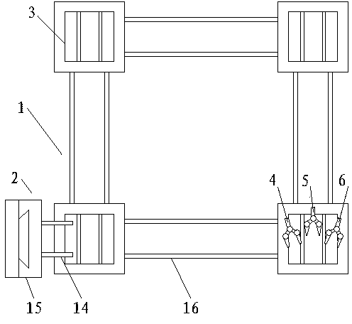
[0034] Such as figure 1 As shown, an automatic shoelace machine of the present invention includes a working area 1 surrounded by four guide rails 16, a positioning device 2 for shoe positioning, a workbench 3 for shoe clamping and a shoelace for wearing. The first manipulator 4, the second manipulator 5 and the third manipulator 6 of the shoelace, the positioning device 2 is arranged on one side of the work area, the first manipulator 4, the second manipulator 5 and the third manipulator 6 are arranged in the work area 1, the first The first manipulator 4, the second manipulator 5 and the third manipulator 6 can be independently controlled and cooperate with each other. The worktable 3 is arranged on the guide rail 16 of the working section 1 . The positioning device 2 includes a positioning pin 14 for being installed in the positioning hole of the shoe, a positioning guide rail 15 and a positioning drive device for driving the positioning pin 14 to move along the positioning...

Embodiment 2

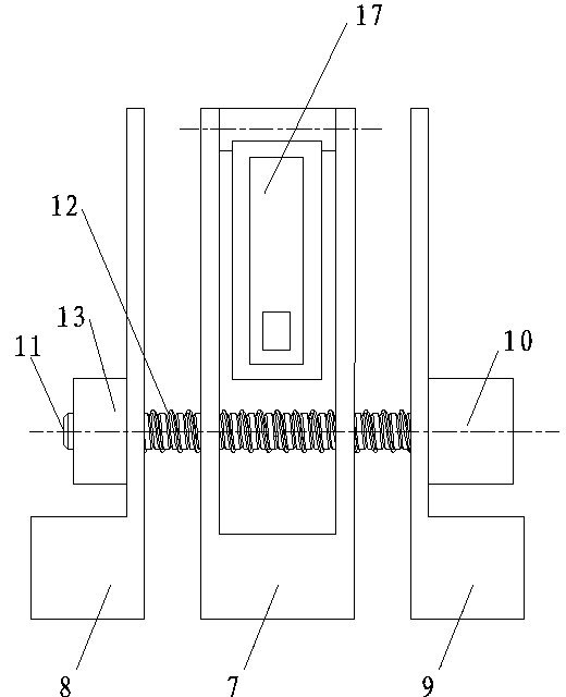
[0049] Such as Figure 4 As shown, the rest is the same as that of Embodiment 1, the difference is that a workbench 3 is provided, and the workbench 3 can move reciprocatingly in the working area. The operator first hangs the shoes on the two positioning pins 14 of the positioning device 2, the worktable drive device drives the worktable 3 to move along the guide rail 16, and moves below the two positioning pins 14, and the positioning drive device drives the positioning pins 14 along the positioning The guide rail 15 moves down, and the shoes are handed over to the workbench 3. The fixed splint 7 of the workbench 3 stretches the inner side of the shoe, and the clamping and positioning drive device drives the movable splints 8 and 9 of the workbench 3 to move to the fixed splint 7 and clamp them. For the shoe, after the above actions are completed, the workbench 3 moves laterally, the shoe is separated from the positioning pin 14, and moves to the designated shoelace perforati...

Embodiment 3

[0051] The rest is the same as that of Embodiment 1, except that two workbenches 3 are provided, and the workbenches 3 can reciprocate in the working area. The operator first hangs the shoes on the two positioning pins 14 of the positioning device 2, the worktable drive device drives the worktable 3 to move along the guide rail 16, and moves below the two positioning pins 14, and the positioning drive device drives the positioning pins 14 along the positioning The guide rail 15 moves down, and the shoes are handed over to the workbench 3. The fixed splint 7 of the workbench 3 stretches the inner side of the shoe, and the clamping and positioning drive device drives the movable splints 8 and 9 of the workbench 3 to move to the fixed splint 7 and clamp them. For the shoe, after the above actions are completed, the workbench 3 moves laterally, the shoe is separated from the positioning pin 14, and moves to the designated shoelace perforation position to wear the shoelace. By arra...


PUM


Abstract

The invention discloses an automatic shoelace threading machine, which comprises a working space consisting of at least two guide rails, a positioning device for positioning shoes, a workbench for clamping the shoes and at least two mechanical hands for threading shoelaces, wherein the positioning device and the mechanical hands are arranged in the working space; the workbench is arranged on the guide rails of the working space, and comprises a fixed clamping plate, movable clamping plates, a shoe tongue clamping plate, a clamping and positioning driving device for driving the movable clamping plates to move, and a shoe tongue clamping plate driving device for driving the shoe tongue clamping plate to move; the movable clamping plates are arranged on the left and right sides of the fixed clamping plate; and the shoe tongue clamping plate is arranged in a groove of the fixed clamping plate. A threading method of the automatic shoelace threading machine is also disclosed. The technical scheme has the beneficial effects that the shoelaces are automatically threaded, so that the shoelace threading speed is effectively increased, the production efficiency of the shoes is improved, and the degree of tightness of shoelace threading is effectively ensured.

Description

technical field [0001] The invention relates to a high-precision optical-mechanical-electrical positioning integrated production equipment, in particular to an automatic shoelace threading machine and a threading method thereof. Background technique [0002] In the prior art, usually after the shoe upper is processed, shoe laces are put on the shoe upper before inserting the shoe last, and then the shoe last is inserted to simulate real people’s feet wearing shoes. , Grinding, desulfurization and shaping, gluing, closing and other processes. For this purpose, the shoe comprises a plurality of eyelets through which laces can pass smoothly, wherein the eyelets are arranged in equal numbers on both sides of the back of the shoe, the laces crossing from the upper eyelet to the lower end of the shoe In my eyes, in order to complete this process, each assembly line in the shoe factory is equipped with a number of people, such as 8 people, standing next to the assembly line to wea...

Claims


Application Information

Patent Timeline
IPC IPC(8): A43C7/00
Inventor 陈竞坤黄剑萍何骏邓建定
Owner 苏州辰戈电子科技有限公司
Why Eureka
Try Eureka