Automatic shoelace threading machine and threading method thereof
A shoelace machine and automatic threading technology, which is applied to footwear, shoe ties, clothing, etc., can solve the problems of slow threading and low efficiency of threading shoelaces, so as to improve the threading speed of shoelaces, ensure accuracy, and guarantee elastic effect
- Summary
- Abstract
- Description
- Claims
- Application Information
AI Technical Summary
Problems solved by technology
Method used
Image
Examples
Embodiment 1
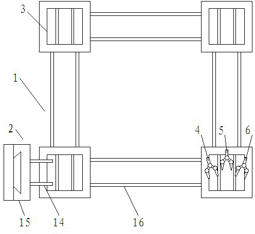
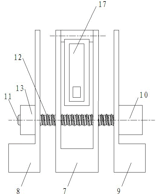
[0034] Such as figure 1 As shown, an automatic shoelace machine of the present invention includes a working area 1 surrounded by four guide rails 16, a positioning device 2 for shoe positioning, a workbench 3 for shoe clamping and a shoelace for wearing. The first manipulator 4, the second manipulator 5 and the third manipulator 6 of the shoelace, the positioning device 2 is arranged on one side of the work area, the first manipulator 4, the second manipulator 5 and the third manipulator 6 are arranged in the work area 1, the first The first manipulator 4, the second manipulator 5 and the third manipulator 6 can be independently controlled and cooperate with each other. The worktable 3 is arranged on the guide rail 16 of the working section 1 . The positioning device 2 includes a positioning pin 14 for being installed in the positioning hole of the shoe, a positioning guide rail 15 and a positioning drive device for driving the positioning pin 14 to move along the positioning...
Embodiment 2
[0049] Such as Figure 4 As shown, the rest is the same as that of Embodiment 1, the difference is that a workbench 3 is provided, and the workbench 3 can move reciprocatingly in the working area. The operator first hangs the shoes on the two positioning pins 14 of the positioning device 2, the worktable drive device drives the worktable 3 to move along the guide rail 16, and moves below the two positioning pins 14, and the positioning drive device drives the positioning pins 14 along the positioning The guide rail 15 moves down, and the shoes are handed over to the workbench 3. The fixed splint 7 of the workbench 3 stretches the inner side of the shoe, and the clamping and positioning drive device drives the movable splints 8 and 9 of the workbench 3 to move to the fixed splint 7 and clamp them. For the shoe, after the above actions are completed, the workbench 3 moves laterally, the shoe is separated from the positioning pin 14, and moves to the designated shoelace perforati...
Embodiment 3
[0051] The rest is the same as that of Embodiment 1, except that two workbenches 3 are provided, and the workbenches 3 can reciprocate in the working area. The operator first hangs the shoes on the two positioning pins 14 of the positioning device 2, the worktable drive device drives the worktable 3 to move along the guide rail 16, and moves below the two positioning pins 14, and the positioning drive device drives the positioning pins 14 along the positioning The guide rail 15 moves down, and the shoes are handed over to the workbench 3. The fixed splint 7 of the workbench 3 stretches the inner side of the shoe, and the clamping and positioning drive device drives the movable splints 8 and 9 of the workbench 3 to move to the fixed splint 7 and clamp them. For the shoe, after the above actions are completed, the workbench 3 moves laterally, the shoe is separated from the positioning pin 14, and moves to the designated shoelace perforation position to wear the shoelace. By arra...
PUM
 Abstract
Description
Claims
Application Information
 - R&D
- Intellectual Property
- Life Sciences
- Materials
- Tech Scout
- Unparalleled Data Quality
- Higher Quality Content
- 60% Fewer Hallucinations
Browse by: Latest US Patents, China's latest patents, Technical Efficacy Thesaurus, Application Domain, Technology Topic, Popular Technical Reports.
© 2025 PatSnap. All rights reserved.Legal|Privacy policy|Modern Slavery Act Transparency Statement|Sitemap|About US| Contact US: help@patsnap.com


