Welding machine suspension bracket

A hanger, welding machine technology, applied in welding equipment, auxiliary welding equipment, welding/cutting auxiliary equipment, etc., can solve the problems of on-site line confusion, low production efficiency, loose joints, etc., to avoid low efficiency and increase welding range. Effect

Inactive Publication Date: 2013-12-04
WUXI ZHONGNENG JINGKE NEW ENERGY TECH
View PDF7 Cites 5 Cited by
  • Summary
  • Abstract
  • Description
  • Claims
  • Application Information

AI Technical Summary

Problems solved by technology

In the case of relatively large welding area, it is necessary to constantly move the position of the welding machine, resulting in low production efficiency
At t

Method used


Image

  • Welding machine suspension bracket

Examples


Example Embodiment

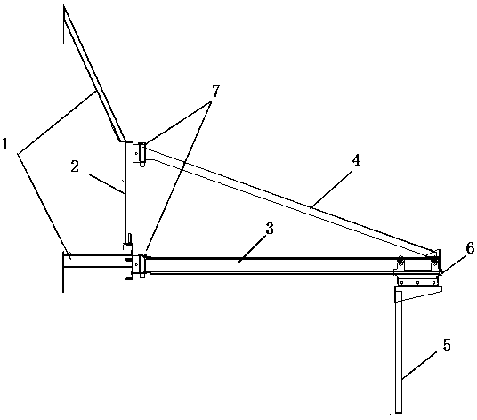
[0008] The present invention will be further described below in conjunction with the accompanying drawings.

[0009] The present invention includes a fixed frame 2 connected to the base 1, an upper bridge frame 4, a sliding bridge frame 3 and a welding machine suspension device 5, and is characterized in that the sliding bridge frame 3 and the upper bridge frame 4 are connected with the fixed frame 2 through a steering shaft component 7 to form a A triangle rotating with the fixed frame 2 as the axis; the welding machine suspension device 5 is installed on the front end of the sliding bridge 3 through the slider 6, and can slide on the sliding bridge 3. Said steering shaft part 7 has a wire passing hole in the middle.

[0010] There are many specific application approaches of the present invention, and the above description is only a preferred embodiment of the present invention. It should be pointed out that for those of ordinary skill in the art, some improvements can also ...


PUM


Abstract

The invention provides a welding machine suspension bracket. The welding machine suspension bracket comprises a fixing frame connected to a base, an upper bridge frame, a sliding bridge frame and a welding machine suspension device. The welding machine suspension bracket is characterized in that the sliding bridge frame and the upper bridge frame are connected with the fixing frame through steering shafts component to form a triangular rotary pair, wherein the triangular rotary pair takes the fixing frame as an axis to rotate; the welding machine suspension bracket is arranged at the front end of the sliding bridge frame through a sliding block, and the welding machine suspension device can slide on the sliding bridge frame. Due to the fact that the steering shaft components and the sliding bridge frame are arranged, a welding machine can move on the suspension bracket, the welding range of the welding machine is effectively increased, and the problems that efficiency is low, lines are messed, contactors are loosened caused by frequent moving of the welding machine equipment during the practical operation process is solved.

Description

technical field [0001] The invention relates to the field of welding equipment, in particular to a welding machine hanger. Background technique [0002] With the increasing size of the equipment, it is mainly relying on the position of the mobile welding machine to achieve full coverage of the welding machine surface of the product. When welding, it is necessary to move the welding equipment continuously to ensure that the welding workpiece is on the welding machine. within the welding range. In the case of a relatively large welding area, it is necessary to constantly move the position of the welding machine, resulting in low production efficiency. At the same time, constantly moving the position of the welding machine will cause problems such as on-site wiring confusion and loose joints, which poses a safety hazard. Contents of the invention [0003] The invention provides a welding machine suspension frame, which can effectively increase the welding effective ...

Claims


Application Information

Patent Timeline
IPC IPC(8): B23K37/02
Inventor 许伟
Owner WUXI ZHONGNENG JINGKE NEW ENERGY TECH
Why Eureka
Try Eureka