Welding mechanism for rail transit

A welding mechanism and rail transit technology, applied in welding equipment, auxiliary welding equipment, welding/cutting auxiliary equipment, etc., can solve the problems of high work intensity, time-consuming and laborious, disintegration of the top cover and bottom plate of the head car, and achieve a wide range of welding. , the effect of increasing the welding range

Active Publication Date: 2020-12-22
浙江泰邦电器有限公司
View PDF9 Cites 0 Cited by
  • Summary
  • Abstract
  • Description
  • Claims
  • Application Information

AI Technical Summary

Problems solved by technology

During assembly welding, the operator first splices the bottom plate of the head car top cover, aligns it visually, and then crouches on the bottom plate of the head car top cover to weld the bottom plate. During the welding process, the operator will Holding a welding torch and a hammer in one hand, knocking the welding slag after welding, and then stepping on the bottom plate of the head car to move to the next welding place. Not only is the work intensive, but it is also easy to make the assembled head The disintegration of the top cover and bottom plate of the car is time-consuming and laborious

Method used


Image

  • Welding mechanism for rail transit
  • Welding mechanism for rail transit
  • Welding mechanism for rail transit

Examples


Embodiment Construction

[0065] In order to make the purpose, technical solutions and advantages of the embodiments of the present invention more clear, the technical solutions in the embodiments of the present invention will be clearly and completely described below in conjunction with the accompanying drawings in the embodiments of the present invention. Obviously, the described embodiments It is a part of embodiments of the present invention, but not all embodiments. Based on the embodiments of the present invention, all other embodiments obtained by persons of ordinary skill in the art without making creative efforts belong to the protection scope of the present invention.

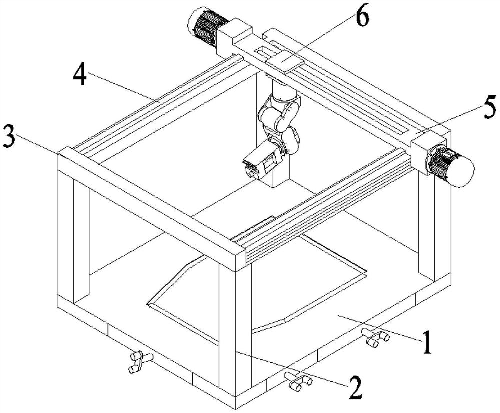
[0066] The embodiment of the present invention provides a rail transit welding mechanism, the welding mechanism includes a base 1, four sets of support columns 2, a beam, a moving seat 5 and a welding assembly 6, exemplary, such as figure 1 As shown; the base 1 is a rectangular plate, and the four sets of support columns 2 are...


PUM


Abstract

The invention belongs to the technical field of rail transit equipment, and particularly relates to a welding mechanism for rail transit. The welding mechanism for rail transit comprises a base, foursets of supporting columns, a cross beam, a movable base and a welding assembly. The cross beam is fixedly installed on the base through a plurality of sets of supporting columns. The cross beam comprises two sets of cross rods and two sets of sliding rails; the two sets of cross rods are parallel and symmetrically arranged; and the two sets of sliding rails are parallel and symmetrically arranged; Two ends of the movable base are movably clamped to the two sets of sliding rails correspondingly. A clamping assembly is movably mounted on the movable base. The welding assembly is movably clampedonto the movable base, so that the welding assembly can reach any point in a plane projection formed by the sliding rails and the cross beam.

Description

technical field [0001] The invention belongs to the technical field of rail transit equipment, in particular to a rail transit welding mechanism. Background technique [0002] Rail transit refers to a type of vehicle or transportation system in which operating vehicles need to run on specific tracks. The most typical rail transit is a railway system composed of traditional trains and standard railways. High-speed rail trains are a type of rail transit. High-speed rail trains are assembled from four major parts during manufacturing: car body, bogie, upper and lower parts of the car and facilities inside the car. The car body part also includes the head car body, which is the car body with a cab, which is mainly assembled and welded by hand. [0003] In the prior art, the upper cover of the head car is assembled on a welding platform, and the upper cover of the head car is assembled and welded by a plurality of plates. During assembly welding, the operator first splices the...

Claims


Application Information

Patent Timeline
Patent Type & Authority Applications(China)
IPC IPC(8): B23K37/02B23K37/04B23K37/08
CPCB23K37/0211B23K37/0252B23K37/0443B23K37/08
Inventor 杨钧元
Owner 浙江泰邦电器有限公司
Why Eureka
Try Eureka