Welding fixing device for automatic brazing equipment

A technology for fixing devices and equipment, which is applied in the direction of welding equipment, auxiliary welding equipment, welding/cutting auxiliary equipment, etc., can solve the problems of difficult metal pipe circumference welding, inability to rotate metal pipes, and insufficient welding strength, etc., to achieve protection and safety. Small workload, good effect

Inactive Publication Date: 2021-03-23
秦宁宁
3 Cites 0 Cited by

AI-Extracted Technical Summary

Problems solved by technology

[0003] At present, when brazing, metal objects need to be fixed, and a welding fixing device needs to be used, but the existing fixing device has the following deficiencies: 1. After the existing welding fixing device has fixed the metal pipe, The metal tubes cannot be rotated, making it difficult to weld the metal tubes circumferentially, resulting in insufficient weld...

Method used

One side of described workbench 1 lower surface is fixedly connected with reinforcing plate 5, and threaded rod 8 runs through reinforcing plate 5, and...

Abstract

The invention discloses a welding fixing device for automatic brazing equipment and belongs to the technical field of welding. The welding fixing device comprises a workbench, a driven belt pulley ring and the automatic brazing equipment mounted on the side surface of the workbench and is characterized in that support columns are fixedly connected to four corners of the lower surface of the workbench, and two mounting plates are arranged on the upper surface of the workbench, one mounting plate is fixedly connected to one side of the upper surface of the workbench, the other mounting plate isslidably connected to the other side of the upper surface of the workbench, and a moving mechanism is fixedly connected to the lower surface of the other mounting plate. According to the welding fixing device for the automatic brazing equipment, a rotating plate A and a rotating plate B rotate downwards to enable a dry powder extinguishing agent to fall down to extinguish fire, so that occurrenceof fire disasters is prevented, and the safety of workers and factories is protected.

Application Domain

Welding/cutting auxillary devicesFire rescue +4

Technology Topic

PhysicsEngineering +5

Image

  • Welding fixing device for automatic brazing equipment
  • Welding fixing device for automatic brazing equipment
  • Welding fixing device for automatic brazing equipment

Examples

  • Experimental program(1)

Example Embodiment

[0031] The present invention will be further described below in conjunction with the examples.
[0032] The following examples are used to illustrate the present invention, but cannot be used to limit the protection scope of the present invention. The conditions in the embodiment can be further adjusted according to the specific conditions, and the simple improvement of the method of the present invention under the premise of the concept of the present invention belongs to the protection scope of the present invention.
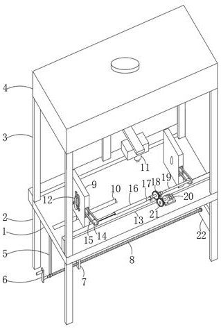
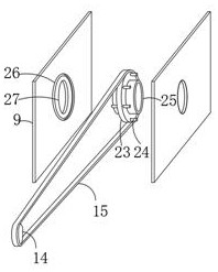
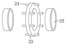
[0033] see Figure 1-9 , the present invention provides a welding fixing device for automatic brazing equipment, including a workbench 1, a driven pulley ring 23 and an automatic brazing equipment 11 installed on the side of the workbench 1, the four corners of the lower surface of the workbench 1 The supporting columns 2 are fixedly connected at all places, and the upper surface of the workbench 1 is provided with two mounting plates 9, one of which is fixedly connected to one side of the upper surface of the workbench 1, and the other mounting plate 9 is slidably connected to the working surface. On the other side of the upper surface of the table 1, and the lower surface of the other mounting plate 9 is fixedly connected with a moving mechanism, and the two mounting plates 9 are hollow, and the two opposite side walls of the mounting plate 9 are provided with through holes 27, and Two relative inner surfaces of the mounting plate 9 are all provided with space-limiting recessed rings 26, and both sides of the driven pulley ring 23 are fixedly connected with the mounting ring 25, and one side of the mounting ring 25 is fixedly connected with the three-jaw chuck 12, and the driven Both the pulley ring 23 and the mounting ring 25 are provided with through grooves, and the outer circumferences on both sides of the driven pulley ring 23 are fixedly connected with a plurality of equidistant distribution and matching with the limit concave ring 26. The limit sliding column 24 is slidably connected with the limit concave ring 26, the driven pulley ring 23 is connected with the drive mechanism, and the drive mechanism is fixedly installed on the upper surface of the U-shaped frame 13, and the U-shaped frame 13 is fixedly connected to the workbench 1 side of the upper surface.
[0034] The four corners of the upper surface of the workbench 1 are fixedly connected with a support plate 3 , and the upper surface of the support plate 3 is fixedly connected with a fire extinguishing structure.
[0035] Described moving mechanism comprises threaded rod 8, and one end of threaded rod 8 is rotatably connected to one side of base plate 22, and base plate 22 is fixedly connected between two supporting posts 2, and the other end of threaded rod 8 is fixedly connected with handle 6, threaded Rod 8 runs through the lower end of limiting plate 7, and threaded rod 8 is threadedly connected with limiting plate 7. Workbench 1 is provided with a limiting groove 10 matched with limiting plate 7, and the upper end of limiting plate 7 passes through the limiting plate 7. The position groove 10 is fixedly connected to the lower surface of the mounting plate 9 , and the lower surface of the mounting plate 9 is in contact with the upper surface of the workbench 1 , and the limiting plate 7 is slidably connected to the limiting groove 10 .
[0036] One side of the lower surface of the workbench 1 is fixedly connected with a reinforcing plate 5, and the threaded rod 8 runs through the reinforcing plate 5, and the threaded rod 8 and the reinforcing plate 5 are connected through bearing rotation; the reinforcing plate 5 can strengthen the threaded rod 8 when it rotates. stability.
[0037] Described driving mechanism comprises rotating rod 17, and the two ends of rotating rod 17 are all sleeved with supporting frame 29, and rotating rod 17 is connected with supporting frame 29 rotations by bearing, and the lower end of supporting frame 29 is fixedly connected on the upper surface of U-shaped frame 13 , one end of the rotating rod 17 is fixedly connected with one end of the telescopic mechanism, the other end of the telescopic mechanism is connected with the driving pulley 14 in rotation, and the other end of the rotating rod 17 is fixedly connected with one end of the connecting rod 19, and the other end of the connecting rod 19 is connected in rotation There is another driving pulley 14, and the driving pulley 14 is connected with the driven pulley ring 23 through the transmission belt 15, and the rotating rod 17 is fixedly fitted with a power mechanism.
[0038] Described power mechanism comprises rotating rod 17, and the middle part of rotating rod 17 is fixedly set with driven gear 18, and one side of U-shaped frame 13 is fixedly installed with motor A20, and the output end of motor A20 is fixedly connected with driving gear 21, and driving Gear 21 and driven gear 18.
[0039] Described telescoping mechanism comprises slide tube 16, slide bar 28 and limit slide bar 30, and one end of slide tube 16 is fixedly connected with an end of rotating bar 17, and slide bar 28 is slidably connected with slide tube 16, and the outer surface of slide bar 28 The limit slide bar 30 is fixedly connected, and the inner surface of the sliding cylinder 16 is provided with a limit chute that matches the limit slide bar 30, and the limit slide bar 30 is slidingly connected with the limit chute; when using the device First, two metal pipes to be welded are respectively passed through the three-jaw chucks 12, the driven pulley ring 23 and the installation ring 25 on the two mounting plates 9, and the metal pipes are clamped by using the three-jaw chucks 12, and at the same time The two ends of the two metal pipes need to be welded in contact. At this time, the threaded rod 8 is rotated by the handle 6, so that the limiting plate 7 drives the mounting plate 9 close to the other mounting plate 9. At this time, the sliding rod 28 slides in the sliding cylinder 16. Thereby making the two metal pipes contact more closely, thereby making the welding effect better, start the automatic brazing equipment 11, make the welding head of the automatic brazing equipment 11 align with the place where the two metal pipes need to be welded, so that the automatic brazing equipment 11 Weld the two metal pipes, and start the motor A20 at the same time, so that the driving gear 21 drives the driven gear 18 to rotate, so that the connecting rod 19 and the telescopic mechanism rotate at the same time, so that the two driving pulleys 14 drive the two driven gears at the same time The pulley ring 23 rotates, so that the two three-jaw chucks 12 drive the two metal pipes to rotate at the same time, so that the automatic brazing equipment 11 performs circumferential welding on the welding place of the two metal pipes, and welds the two metal pipes together , so as to facilitate the circumferential welding of metal pipes, so that the welding range is wider, the welding effect is better, and the welding strength is stronger. The workload of the staff, while protecting the staff.
[0040] The fire extinguishing structure includes a fire extinguishing box 4, a dry powder fire extinguishing agent (such as ammonium phosphate powder) is placed in the fire extinguishing box 4, the lower surface of the fire extinguishing box 4 is fixedly connected to the upper end of the support plate 3, and the lower side wall of the support plate 3 is opened There is a through groove, and the two opposite sides of the through groove are rotatably connected with the rotating plate A31 and the rotating plate B32, and the close sides of the rotating plate A31 and the rotating plate B32 are fixedly connected with the sealing plate 42, and the two sealing plates 42 are staggered It is provided that the upper surfaces of the rotating plate A31 and the rotating plate B32 are provided with a switch mechanism.
[0041] The switch mechanism includes a vertical plate A33 and a vertical plate B38, the vertical plate A33 is fixedly connected to one side of the upper surface of the rotating plate B32, and the vertical plate B38 is fixedly connected to the side of the upper surface of the rotating plate A31 close to the vertical plate A33, and the vertical plate One side of B38 is fixedly connected with two springs 39, and one end of spring 39 away from vertical plate B38 is fixedly connected to one side of connecting plate 40, and the two ends of the other side of connecting plate 40 are all fixedly connected with clip 41, and The middle part of the other side of the connecting plate 40 is fixedly connected with the top column 35, and the vertical plate A33 is provided with a clamping hole 34 matching the clamping column 41, and the end of the clamping column 41 away from the connecting plate 40 is located in the clamping hole 34, and The clamping column 41 is slidingly connected with the clamping hole 34, two telescopic rods 45 are arranged between the vertical plate B38 and the connecting plate 40, and the telescopic rods 45 are located in the spring 39, and the inner top surface of the fire extinguishing box 4 is fixedly equipped with an electric push rod 37 , and the output end of the electric push rod 37 is fixedly connected with the jacking ball 36, and the jacking ball 36 is opposite to the jacking column 35; since the clamping column 41 is located in the clamping hole 34, the rotating plate A31 and the rotating plate B32 are all in a horizontal state, so that the two The two sealing plates 42 are in contact with each other, thereby sealing the lower side wall of the fire extinguishing box 4.
[0042] The lower surface of the rotating plate A31 is fixedly connected with a fire alarm 43 and a PLC controller 44, and the PLC controller 44 is electrically connected with the fire alarm 43 through a wire; When the device catches fire, the fire alarm 43 detects the flame and sends an alarm, and the fire alarm 43 transmits a signal to the PLC controller 44 at the same time, so that the PLC controller 44 sends a start model to the electric push rod 37, and the electric push rod 37 Start and make its output end move down, so that the top ball 36 moves down and contacts with the top column 35, the top ball 36 pushes the top column 35 to the left, the spring 39 is compressed, and the telescopic rod 45 is compressed, thereby driving the clamp column 41 to The vertical plate B38 moves so that the clamping column 41 leaves the clamping hole 34. At this time, the rotating plate A31 and the rotating plate B32 rotate downwards so that the dry powder fire extinguishing agent falls to extinguish the fire, thereby preventing the occurrence of a fire and protecting the safety of workers and factories.
[0043] The welding method of this device:
[0044] When using this device, at first two metal pipes that need to be welded pass through the three-jaw chuck 12 on the two mounting plates 9, the driven pulley ring 23 and the installation ring 25, and use the three-jaw chuck 12 to put the metal pipe Clamping, and at the same time make the two ends of the two metal pipes need to be welded in contact, at this time, turn the threaded rod 8 through the handle 6, so that the limiting plate 7 drives the mounting plate 9 close to the other mounting plate 9, and now the sliding rod 28 is sliding Sliding inside the barrel 16, so that the two metal pipes are in closer contact, so that the welding effect is better, start the automatic brazing equipment 11, so that the welding head of the automatic brazing equipment 11 is aligned with the place where the two metal pipes need to be welded, Make the automatic brazing equipment 11 weld the two metal pipes, and start the motor A20 at the same time, so that the driving gear 21 drives the driven gear 18 to rotate, so that the connecting rod 19 and the telescopic mechanism rotate simultaneously, so that the two driving pulleys 14 simultaneously Drive the two driven pulley rings 23 to rotate, so that the two three-jaw chucks 12 drive the two metal pipes to rotate at the same time, so that the automatic brazing equipment 11 performs circumferential welding on the welds of the two metal pipes, and the two The metal pipes are welded together, which facilitates the circumferential welding of the metal pipes, which makes the welding range wider, the welding effect is better, and the welding strength is stronger. At the same time, the staff does not need to rotate the metal pipes to achieve automatic circumference Welding reduces the workload of the staff and protects the staff at the same time.
[0045] What needs to be explained in the plan is:
[0046] The automatic brazing equipment 11, the motor A20, the electric push rod 37, the fire alarm 43 and the PLC controller 44 are all common parts of the prior art, and the models used etc. can be customized according to actual usage requirements. The power supply interface of the device is connected to the power supply system through a switch (not shown in the figure) and a wire (not shown in the figure), so as to realize its control. The circuits and controls involved are all existing technologies and are well known in the current art. No more details are given here.
[0047] In the description of the present invention, it should be noted that the terms "center", "upper", "lower", "left", "right", "vertical", "horizontal", "front", "rear" etc. The indicated orientation or positional relationship is based on the orientation or positional relationship shown in the drawings, and is only for the convenience of describing the present invention and simplifying the description, rather than indicating or implying that the referred device or element must have a specific orientation, or in a specific orientation. structure and operation, so it should not be construed as a limitation to the present invention. In the present invention, it should also be explained that the terms "installation" and "connection" should be interpreted in a broad sense, for example, it can be fixed connection or detachable connection, or The integrated connection may also be a mechanical connection, or an indirect connection through an intermediary, and the specific meaning of the terms in the present invention may be understood according to specific circumstances.
[0048] Although the embodiments of the present invention have been shown and described, those skilled in the art can understand that various changes, modifications and substitutions can be made to these embodiments without departing from the principle and spirit of the present invention. and modifications, the scope of the invention is defined by the appended claims and their equivalents.

PUM

no PUM

Description & Claims & Application Information

We can also present the details of the Description, Claims and Application information to help users get a comprehensive understanding of the technical details of the patent, such as background art, summary of invention, brief description of drawings, description of embodiments, and other original content. On the other hand, users can also determine the specific scope of protection of the technology through the list of claims; as well as understand the changes in the life cycle of the technology with the presentation of the patent timeline. Login to view more.

Similar technology patents

Efficient and environment-friendly pestcide

InactiveCN105028469Arich varietywide range
Owner:NANTONG HUIRAN BIOLOGICAL SCI & TECH

Quick coating withdrawing equipment

PendingCN107931257AImprove efficiencywide range
Owner:DONGGUAN FIRSTOP M & E EQUIP

Classification and recommendation of technical efficacy words

  • good effect
  • wide range

Multifunctional operation type underwater robot

InactiveCN106143841AEasy to salvagewide range
Owner:QINGDAO SEA ROBOT CO LTD

Big-data analysis system

Owner:北京天平检验行有限公司

Vehicle trajectory determination method and device, electronic equipment and computer storage medium

PendingCN112597822Awide rangeBroad perspective
Owner:CHINA INTELLIGENT & CONNECTED VEHICLES (BEIJING) RES INST CO LTD
Why Eureka
Try Eureka