A welding equipment suitable for valve manufacturing

A technology of welding equipment and valves, which is applied in welding equipment, auxiliary welding equipment, welding/cutting auxiliary equipment, etc., can solve the problems of large welding limitations, welding virtual welding, and increased defective rate, and achieve simple and stable structure, improve Effect of service life and reduction of defective rate

Active Publication Date: 2021-12-28
合飞阀门有限公司
View PDF8 Cites 1 Cited by
  • Summary
  • Abstract
  • Description
  • Claims
  • Application Information

AI Technical Summary

Problems solved by technology

[0005] In order to solve the above technical problems, the present invention provides a kind of welding equipment suitable for valve production and manufacturing, to solve the problem that the existing welding equipment for valve production and manufacturing does not have a welding coaxial fixing structure, and the valve assembly starts welding when the basic assembly of the valve assembly is not in place. The service life of the valve is greatly reduced, and the inaccurate butt joint of the valve components leads to "false welding" in the welding, which increases the defective rate; there is no ring valve welding device, and the welding position needs to be adjusted frequently, resulting in the inability to quickly weld the valve work, the welding speed is slow, which affects production efficiency; the welding torch positioning structure is not set, and the welding position required by different valves cannot be met. While the welding limitations are large, the inability to accurately adjust the welding angle of the welding torch will reduce the quality of the welding process.

Method used


Image

  • A welding equipment suitable for valve manufacturing
  • A welding equipment suitable for valve manufacturing
  • A welding equipment suitable for valve manufacturing

Examples


Embodiment 1

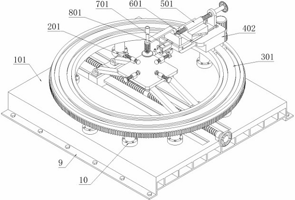
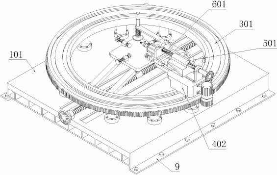
[0044] as attached figure 1 to attach Figure 17 Shown:

[0045] The present invention provides a kind of welding equipment suitable for the production and manufacture of valves, which includes a supporting device 1; two first mounting plates 9 are fixedly connected to the bottom of the supporting device 1, ten supporting columns 10 are installed on the supporting device 1, and ten supporting A running track part 3 is fixedly connected to the column 10; four positioning devices 2 are fixedly connected to the support device 1, and the structures on the four positioning devices 2 are the same; a driving device 4 is installed on the running track part 3, and the driving device 4 An adjustment part 5 is installed on it; an upper mold positioning device 8 is installed on the driving device 4; a welding support part 6 is rotatably connected to the driving device 4; a welding part 7 is installed on the welding support part 6.

[0046] as attached Figure 4 , Figure 5 , Figure ...

Embodiment 2

[0049] as attached Figure 6 As shown, the positioning device 2 includes: a positioning support block 201, four positioning support blocks 201 are provided, and the four positioning support blocks 201 are fixedly connected to the second mounting plate 105 respectively; Threaded hole; Positioning propulsion shaft 202, positioning propulsion shaft 202 is provided with four, and four positioning propulsion shafts 202 are respectively threaded on four positioning support blocks 201; Positioning propulsion shaft 202 front end is spherical structure; Positioning device 2 is provided The propulsion can be realized by rotating and positioning the propulsion shaft 202, and the structure is simple and stable. At the same time, the multi-directional positioning of the valve assembly can be realized by setting four positioning propulsion shafts 202 to thread on the positioning support block 201 respectively. Adjusting the four positioning propulsion shafts 202 can realize the adjustment o...

Embodiment 3

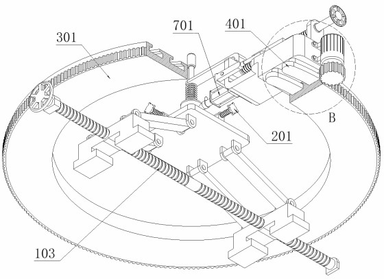
[0052] as attached Figure 5As shown: on the basis of the first embodiment, this embodiment provides another lifting and driving structure of the second mounting plate 105, which solves the need to manually rotate the two-way screw 103 during the actual lifting operation of the second mounting plate 105 To drive, the problem of slow lifting speed, the support device 1 includes: a support base plate 101, the support base plate 101 is fixedly connected on the two first mounting plates 9; the support base plate 101 is provided with two slide grooves; the lifting drive block 102, Two lifting drive blocks 102 are provided with two, and the two lifting drive blocks 102 are all slidably connected in two chutes on the support base plate 101; the two lifting drive blocks 102 are all provided with threaded holes; the two-way screw rod 103, the two-way screw The rod 103 is connected to the support base plate 101 through the support rotating shaft; the two-way screw rod 103 is provided wi...


PUM


Abstract

The invention provides a welding equipment suitable for the production and manufacture of valves, including a support device; two first mounting plates are fixedly connected to the bottom of the support device, ten support columns are installed on the support device, and the ten support columns are fixed The running track is connected; four positioning devices are fixedly connected to the supporting device, and the structures on the four positioning devices are the same; the driving device is installed on the running track, and the adjusting part is installed on the driving device; the driving device is installed with The upper mold positioning device; the welding support part, which is rotatably connected to the driving device; the welding part is installed on the welding support part, and the positioning device is installed, and the propulsion can be realized by rotating and positioning the propulsion shaft. The structure is simple and stable. By adjusting the four positioning propulsion shafts, the coaxiality of the valve parts and the running track can be adjusted, which effectively improves the welding accuracy of the valve, greatly reduces the defective rate, and avoids the occurrence of "virtual welding" at the same time.

Description

technical field [0001] The invention belongs to the technical field of valve production, and more specifically relates to welding equipment suitable for valve production and manufacture. Background technique [0002] Valves are the control components in the fluid delivery system. They have the functions of cut-off, adjustment, diversion, prevention of reverse flow, pressure stabilization, diversion or overflow pressure relief. Valves can be used to control air, water, steam, various corrosive media, mud, etc. Due to the important role of valves in the flow of various types of fluids such as oil, liquid metal and radioactive media, the assembly and welding of valves is particularly important. At this time, welding equipment for valve manufacturing must be used to assist in the completion Valve welding work. [0003] For example, the application number: CN201811457614.7 involves automatic valve welding equipment, including electric push rod, turntable, main shell, screw, moto...

Claims


Application Information

Patent Timeline
Patent Type & Authority Patents(China)
IPC IPC(8): B23K37/00B23K37/04B23K37/02
CPCB23K37/00B23K37/0443B23K37/0247
Inventor 闫浩
Owner 合飞阀门有限公司
Why Eureka
Try Eureka