
Mold

A mold and mold base technology, which is applied in the field of molds, can solve problems such as large deviations in machining accuracy, deformation of guide posts, and difficult stability of finished product forming, and achieve the effect of convenient installation and separation, and not easy to be displaced

Inactive Publication Date: 2013-12-04
HONG FU JIN PRECISION IND (SHENZHEN) CO LTD +1
View PDF0 Cites 2 Cited by
  • Summary
  • Abstract
  • Description
  • Claims
  • Application Information

AI Technical Summary

Problems solved by technology

As the function of the guide rail, if the eccentric angle of the guide post is too large, that is, the deviation of the machining accuracy is large, or after the mold has been used for a period of time, the guide post may be deformed due to long-term impact, which will change the eccentric value of the guide post. As a result, the finished product is vulnerable to the interference of the mold structure during demoulding, which affects the variation of the mold cavity depth when the finished product is formed, and the finished product will not be stable when it is formed
[0003] The removal of the guide post of the existing mold structure must first disassemble the male plate before taking it out, and this action cannot be operated on the injection molding machine

Method used


Image

  • Mold
  • Mold
  • Mold

Examples


Embodiment Construction

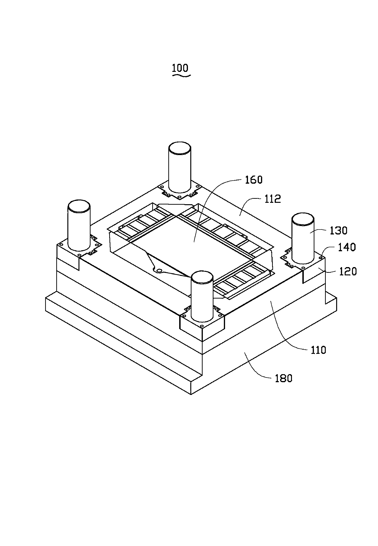
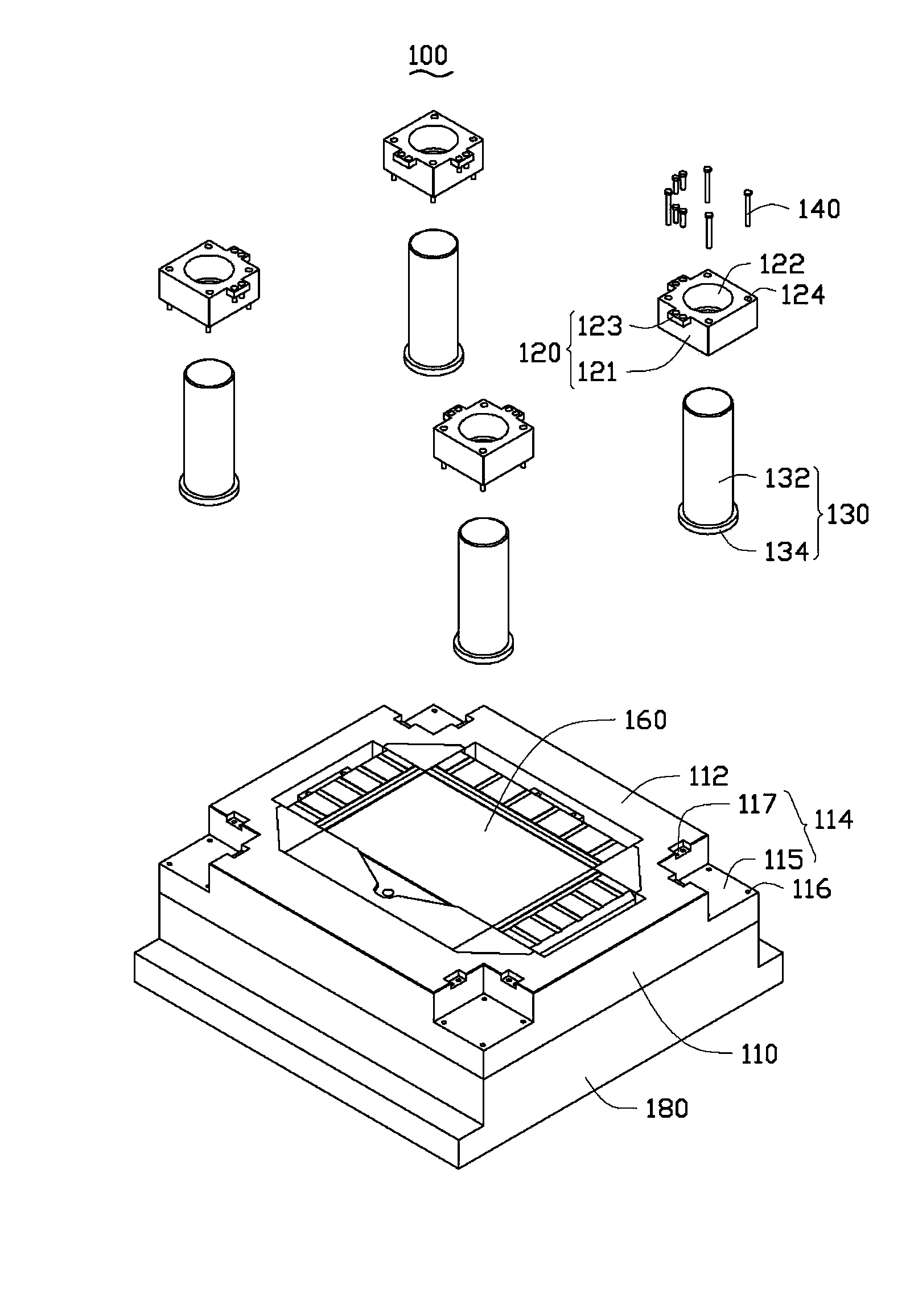
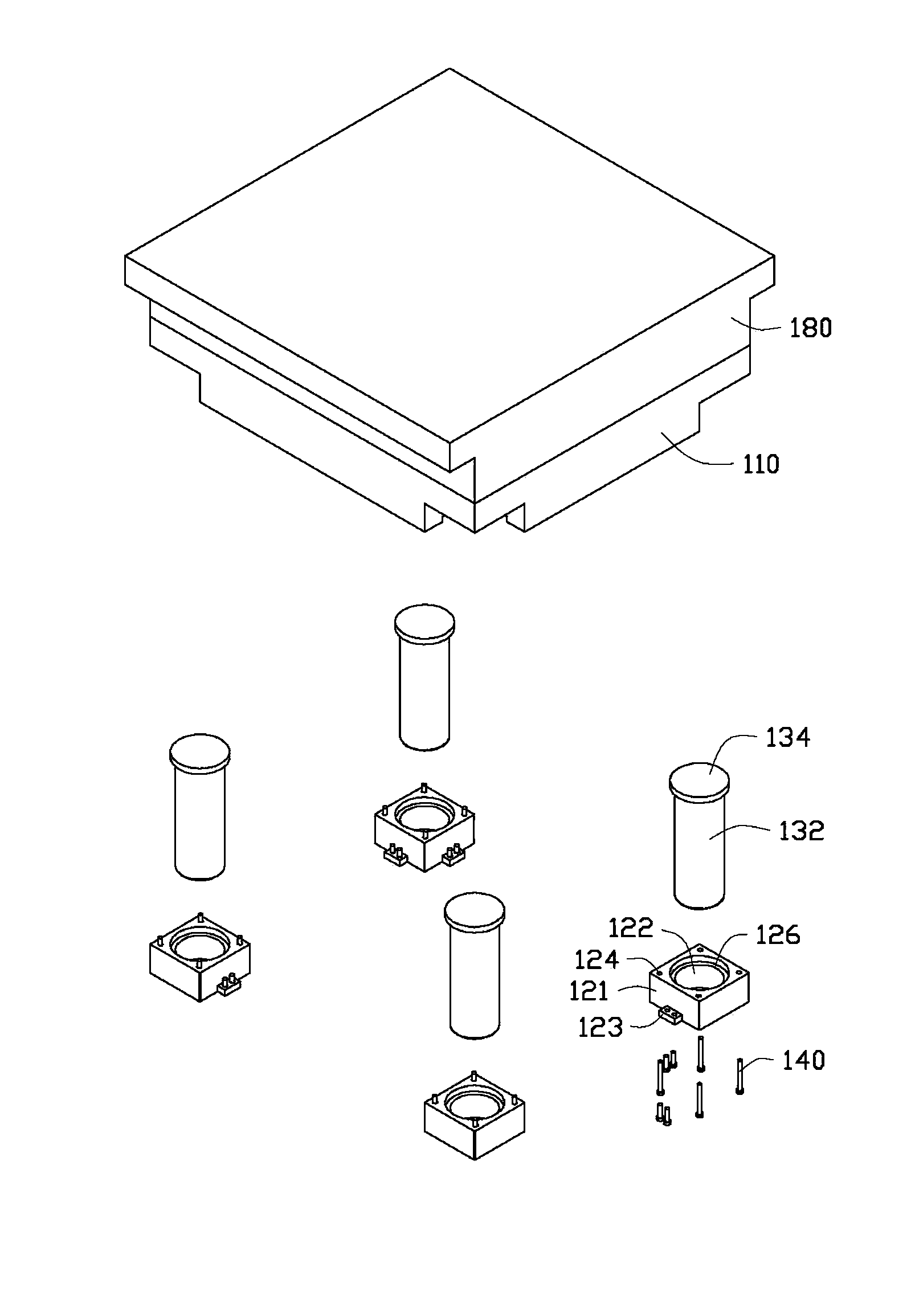
[0015] See Figure 1 to Figure 3 , The mold 100 provided by the embodiment of the present invention includes a mold base 110, a plurality of guide pillar fixing blocks 120, a plurality of guide pillars 130, and a plurality of screws 140. The mold 100 is used as a sub-mold. In injection molding, the mold 100 is usually used as a male mold, which is formed in cooperation with another sub-mold, that is, a female mold.

[0016] The mold base 110 has a parting surface 112 for separating products. A plurality of grooves 114 are formed on the edge of the parting surface 112. Each of the grooves 114 is provided with a plurality of screw fitting holes 116. In this embodiment, the parting surface 112 is rectangular, and the plurality of grooves 114 includes four grooves 114 located at four corners of the parting surface 112 and exposed to the side of the mold base 110. Each groove 114 includes a main groove 115 and two sub grooves 117 communicating with the main groove 115. Each of the m...


PUM


Abstract

The invention relates to a mold comprising a mold seat, a plurality of guide column fixing blocks, a plurality of guide columns, and a plurality of screws. The mold seat comprises a sub-mold surface. A plurality of recesses are arranged on the edge of the sub-mold surface. A plurality of screw matching holes are arranged at each recess. Each guide column fixing block is used to be engaged into one recess. A through guide hole and a plurality of screw through holes are arranged in each guide column fixing block. Each guide column comprises a guide rod part and a rim positioned on the bottom of the guide rod and protruding outwards. The outer diameter of the rim is larger than the diameter of the guide hole. The rim of each guide column is set on the recess, and the guide rod part penetrates a guide hole. Each screw penetrates a screw through hole, and is fixed into a screw matching hole, such that the guide column fixing block is fixed into a corresponding recess. The mold as a sub-mold can be used in cooperation with another sub-mold provided with a guide sleeve.

Description

Technical field [0001] The invention relates to a mold. Background technique [0002] In the mold, no matter the two-platen mold or the three-platen mold, the guide post is an indispensable part. The purpose is to ensure that the fixed side and the movable side of the mold are not caused by the deviation of the guide post and the guide sleeve during the clamping action. The mold components are damaged. As the function of the guide rail, if the eccentric angle of the guide post is too large, that is, the machining accuracy deviation is large, or the mold is used for a period of time, the guide post may be deformed due to long-term impact, which will change the eccentric value of the guide post. As a result, the finished product is susceptible to interference from the mold structure during demolding, which affects the cavity depth variation when the finished product is formed, and the finished product will be difficult to stabilize when it is formed. [0003] The guide post of the ...

Claims


Application Information

Patent Timeline
IPC IPC(8): B29C45/26
Inventor 王佳铭
Owner HONG FU JIN PRECISION IND (SHENZHEN) CO LTD
Learn More