Towel wringing device

A wringer and towel technology, which is applied in the field of kitchen and bathroom hardware, can solve the problems of towel stretching, fluff easy to fall, and bacterial growth, etc., and achieve the effect of simple structure and suitable for production

Inactive Publication Date: 2013-12-04
SUZHOU SHENGNENG MACHINERY
View PDF6 Cites 6 Cited by
  • Summary
  • Abstract
  • Description
  • Claims
  • Application Information

AI Technical Summary

Problems solved by technology

[0002] In daily life, if the wet towel is directly hung on the towel rack, the dripping water will make the ground slippery. At the same time, the wet towel is eas...

Method used


Image

  • Towel wringing device
  • Towel wringing device
  • Towel wringing device

Examples


Embodiment Construction

[0014] Further description will be given below in conjunction with the accompanying drawings

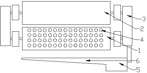
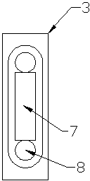
[0015] Such as Figure 1~3 As shown, a towel wringer, the towel wringer includes a drainage stick 1, a pressing stick 2, a water tank 5, a bracket 3, a water diversion tank 6, and the drainage stick 1, a pressing stick 2 and a bracket 3 Rotationally connected, the axes of the drainage roller 1 and the compression roller 2 are parallel to each other, there is a gap between the outer wall of the compression roller 2 and the outer wall of the drainage roller 1, and the drainage roller 1 is a hollow structure with one end sealed and the other open. Drainage holes 4 are densely covered on the drainage stick 1, and the drainage holes 4 run through the inner wall and the outer wall of the drainage stick 1. The lower end of the drainage stick 1 is provided with a water diversion groove 6 equal in length to the drainage stick 1. The drainage stick 1 A water tank 5 is arranged below one end o...


PUM


Abstract

The invention discloses a towel wringing device. According to the invention, by the towel wringing device arranged on the wall, wringing on a towel is implemented; two rotating rods are used for squeezing the towel to carry out drainage and meanwhile, by forming drainage holes in one rotating rod, removal of water generated in the process of wringing the towel is implemented; collection of the water is implemented by a water containing tank and meanwhile, a gradually expanding structure inside the drainage rod is more beneficial to rapid removal of the water and prevents the water in the drainage rod from permeating into the towel again. The towel wringing device has the advantages of simple structure, suitability for production and the like.

Description

technical field [0001] The invention designs a towel wringer, which belongs to the field of kitchen and bathroom hardware. Background technique [0002] In daily life, if the wet towel is directly hung on the towel rack, the dripping water will make the ground slippery. At the same time, the wet towel is easy to cause the growth of bacteria. Frequent manual wringing of the towel will damage the towel Causes severe stretching, making fluff planted on towels easy to fall off. Contents of the invention [0003] The object of the present invention is to provide a technical solution capable of solving the above problems. [0004] The present invention is realized by following method: [0005] A towel wringer, the towel wringer includes a draining stick, a pressing stick, a water tank, a bracket, and a water guide tank, the draining stick, the pressing stick and the bracket are rotatably connected, and the draining stick and the pressing stick The axes are parallel to each ot...

Claims


Application Information

Patent Timeline
IPC IPC(8): D06F45/02
Inventor 杭林生
Owner SUZHOU SHENGNENG MACHINERY
Why Eureka
Try Eureka