Method for sending control signaling, method for detecting control signaling, terminal and base station

A technology for controlling signaling and sending methods, applied in the field of communication, can solve problems such as too many channel estimation times and high terminal complexity, and achieve the effects of reducing channel estimation times, reducing implementation complexity, and reducing detection delay

Active Publication Date: 2018-03-23
ZTE CORP
View PDF4 Cites 0 Cited by
  • Summary
  • Abstract
  • Description
  • Claims
  • Application Information

AI Technical Summary

Problems solved by technology

[0029] Embodiments of the present invention provide a method for sending control signaling, a method for detecting control signaling, a terminal, and a base station, so as to solve the problem caused by too many channel estimation times in the existing control channel detection technology. The complexity problem

Method used


Image

  • Method for sending control signaling, method for detecting control signaling, terminal and base station
  • Method for sending control signaling, method for detecting control signaling, terminal and base station
  • Method for sending control signaling, method for detecting control signaling, terminal and base station

Examples


Embodiment 1

[0086]The base station sends the control signaling on the downlink transmission resources of the second control signaling area. When the base station sends the downlink control signaling, there are several options for selecting the size of the control signaling detection to perform self-adaptation of the code rate during the transmission of the control signaling. Several different aggregation levels are defined for eCCE-based:

[0087] Aggregation level N(1), aggregation level N(2), aggregation level N(3), aggregation level N(4), where N(1)-N(4) are integers. The common values ​​are 1, 2, 4, 8 respectively. This is not limited to this value, nor is it limited to 4 aggregation levels, and may also be 2, 3 aggregation levels and other situations.

[0088] For the base station and the terminal, the following mapping relationship can be agreed upon:

[0089] If ePDCCH candidates occupy one eCCE in the RB, and the eCCE corresponds to a resourceset, determine the DMRS port corresp...

Embodiment 2

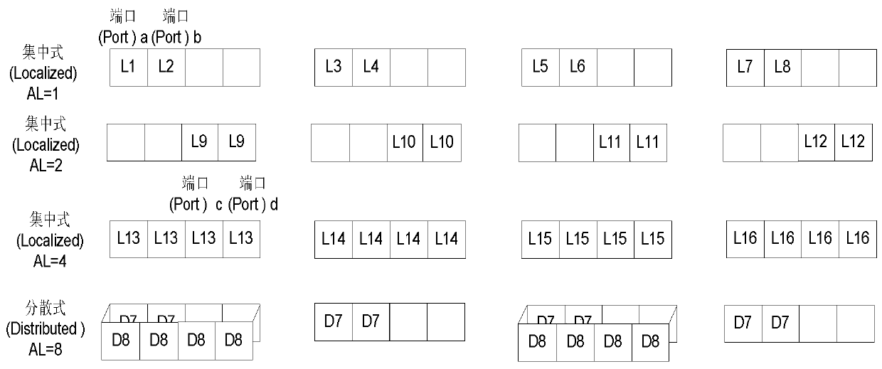
[0108] In the case of embodiment one, it is also possible to pass Figure 4 The configuration shown minimizes the complexity of channel estimation:

[0109] The ePDCCH candidates at aggregation level 1 have 2 candidates in each RB, including Resource set2 and 3 respectively, and the used DMRS ports are a and b, corresponding to 8 and 10 respectively.

[0110] The ePDCCH candidates at aggregation level 2 have a candidate in each RB. The candidate contains the aggregation of Resource set2 and 3 in the RB. The two Resource sets correspond to a DMRS port, because the ePDCCH candidates at aggregation level 1 occupy resources The DMRS port sets corresponding to the set are port8 and 10, and due to the need to meet the existence of the subset relationship, the DMRS port used can only be port8 or port 10; the specific use of port8 or port10 can be determined according to the high-level signaling issued by the base station.

[0111] The ePDCCH candidates under aggregation level 4 have...

Embodiment 3

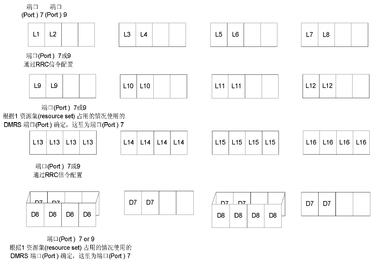
[0117] In the case of embodiment one, it is also possible to pass Figure 5 The configuration shown minimizes the complexity of channel estimation:

[0118] For ePDCCH candidates at aggregation level 1, there is one candidate in each RB, including Resource set0, and the used DMRS port is a, corresponding to port 7.

[0119] The ePDCCH candidates at aggregation level 2 have a candidate in each RB. The candidate contains the aggregation of Resource set0 and 1 in the RB. The two Resource sets correspond to a DMRS port, because the resources occupied by ePDCCH candidates at aggregation level 1 The DMRS port set corresponding to the set is port7, and the DMRS port used is port7 because of the need to satisfy the existence of the subset relationship.

[0120]The ePDCCH candidates under aggregation level 4 have 1 candidate in each RB, and the candidates contain all 4 Resource sets in the RB, and the 4 Resource sets correspond to a DMRSport. Because the ePDCCH candidates at aggregati...


PUM


Abstract

The present invention provides a method for sending control signaling, a method for detecting control signaling, a terminal, and a base station, wherein the detection method includes: the terminal receiving configuration signaling carrying candidate control signaling transmission resource location information sent by the base station; the terminal Determine the aggregation level N(1)...N(n) to be detected according to the configuration signaling, and determine the current aggregation level N(j) according to the DMRS port set used in the RB according to the candidate position under the aggregation level N(i) The set of DMRS ports used in the RB for the candidate position of the candidate position, or the set of DMRS ports used in the RB according to the candidate position of any aggregation level under the aggregation level N(1)...N(n) is the set of DMRS ports used in the RB The subset of the DMRS port set used by the candidate positions under N(p) is used to determine the DMRS port set used by the candidate positions under any aggregation level. The channel estimation times and implementation complexity can be reduced by adopting the present invention.

Description

technical field [0001] The present invention relates to the communication field, in particular to a method for sending control signaling, a method for detecting control signaling, a terminal and a base station. Background technique [0002] In the Long term evolution (LTE for short) system and the added LTE (LTE-Advance) system, the downlink physical layer control signaling includes the downlink grant (DL Grant) information that the terminal needs to know about the downlink transmission and the information that the UE needs to know. The uplink grant (UL Grant) information related to uplink transmission is used to indicate various transmission related information such as transmission resource location, modulation and coding mode, etc. These physical layer control signaling are transmitted on the Physical Downlink Control Channel (PDCCH) . The physical layer control signaling here mainly refers to the user-specific control signaling of the physical layer. [0003] In Release...

Claims


Application Information

Patent Timeline
Patent Type & Authority Patents(China)
IPC IPC(8): H04W72/04H04L5/00H04L25/02
Inventor 陈艺戬戴博左志松张文峰
Owner ZTE CORP
Why Eureka
Try Eureka