fuel dispenser

A technology of fuel distributor and fuel valve, which is applied in the direction of fuel injection device, liquid fuel feeder, charging system, etc. It can solve the problems of mass loss and achieve the effect of compact structure, simple installation and reliable fuel dosing

Inactive Publication Date: 2016-02-10
ROBERT BOSCH GMBH
View PDF6 Cites 0 Cited by
  • Summary
  • Abstract
  • Description
  • Claims
  • Application Information

AI Technical Summary

Problems solved by technology

This results in a loss of quality during retrofitting

Method used


Image

  • fuel dispenser
  • fuel dispenser

Examples


Embodiment Construction

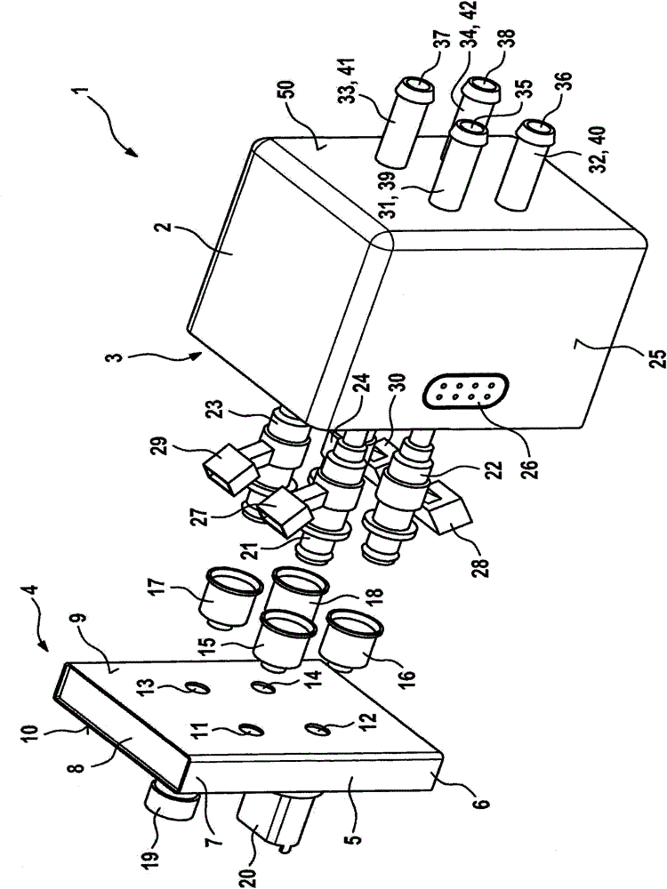
[0015] figure 1 An exemplary embodiment of the fuel distributor 1 is shown in a schematic exploded perspective view. The fuel distributor 1 can be used in particular as an injection block 1 of a fuel injection system for a hybrid compression, externally ignited internal combustion engine. The fuel distributor 1 is particularly suitable here for distributing natural gas to a plurality of cylinder chambers of an internal combustion engine.

[0016] The fuel distributor 1 has a housing 2 with an opening 3 . Furthermore, a fuel distributor block 4 is provided, which closes the opening 3 of the housing 2 in the assembled state. In this case, the fuel distributor block 4 is inserted into the opening 3 of the housing 2 . The fuel distributor block 4 has a tubular base body 5 with a quadrangular outline. The two ends 6, 7 of the tubular base body 5 are closed by a closure piece 8, wherein, in the attached figure 1 The closure tab 8 is shown and labeled in . In this case, the clo...


PUM


Abstract

A fuel distributor (1), which serves in particular as an injector block for fuel injection systems of mixture-compressing, applied-ignition internal combustion engines, comprises a housing (2), a fuel distribution piece (4) which is arranged on an orifice (3) of the housing (2), a first fuel valve (21), and at least one second fuel valve (22). Here, the first fuel valve (21) is connected via a valve cup (15) to a first outlet (11) of the fuel distribution piece (4). The second fuel valve (22) is connected via a valve cup (16) to a second outlet (12) of the fuel distribution piece (4). Furthermore, the first fuel valve (21) and the second fuel valve (22) are arranged within the housing (2). This permits a compact and robust design of the fuel distributor (1).

Description

technical field [0001] The invention relates to a fuel distributor, in particular for distributing natural gas to fuel injection valves. In particular, the invention relates to a fuel distributor for a fuel injection device of a hybrid compression, externally ignited internal combustion engine. Background technique [0002] Hybrid compression, external ignition internal combustion engines are suitable for operation on gasoline and natural gas. However, suitable installation space and suitable fastening are necessary, in particular in the engine compartment of a motor vehicle, for initial installation or retrofitting for operation with natural gas. Since a large number of components are required for the dispensing of natural gas fuel, which is additionally implemented in addition to the gasoline fuel injection system, these components are relatively complex to install and fasten. It is also required here that the configuration of the components for natural gas injection be ...

Claims


Application Information

Patent Timeline
Patent Type & Authority Patents(China)
IPC IPC(8): F02M37/00F02M21/02F02M55/02
CPCF02D19/027F02M21/0215F02M21/0245F02M21/0281F02M55/025Y02T10/30
Inventor M·格纳J·卡夫卡
Owner ROBERT BOSCH GMBH
Why Eureka
Try Eureka