Optical accelerometer
An accelerometer, directional acceleration technology, applied in the field of inertial sensing technology and precision measurement, to achieve the effect of improving detection sensitivity, high resolution, and avoiding mechanical coupling of motion
- Summary
- Abstract
- Description
- Claims
- Application Information
AI Technical Summary
Problems solved by technology
Method used
Image
Examples
Embodiment 1
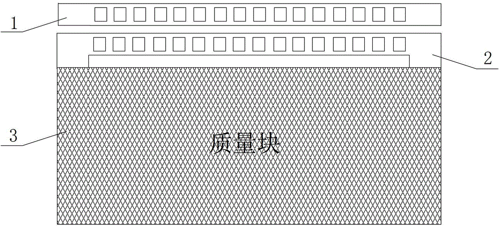
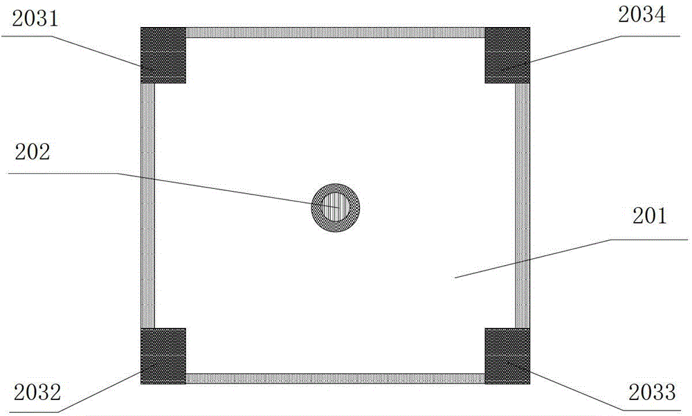
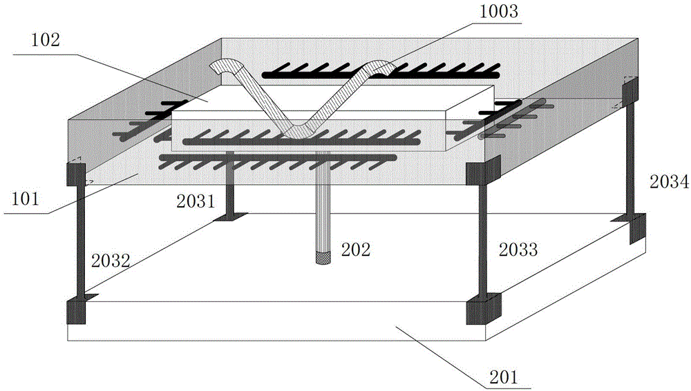
[0054] figure 1 It is a schematic diagram of the plane structure of the acceleration plane detection module in the XY axis direction, figure 2 A schematic diagram of the supporting module structure, image 3 It is a schematic diagram of the three-dimensional structure of a new multi-axis optical accelerometer, Figure 4 It is a schematic diagram of the photonic crystal cavity structure in the X-axis direction of the acceleration plane detection module in the XY-axis direction, Figure 5 It is a schematic diagram of the structure of the photonic crystal cavity in the Y-axis direction of the acceleration plane detection module in the XY-axis direction, Figure 6 It is a schematic diagram of a new multi-axis optical accelerometer detection module, as shown in the figure: the optical accelerometer provided by the present invention includes a detection module and a detection module; the detection module is used to convert the displacement change produced by the acceleration of t...
Embodiment 2
[0090] The difference between this embodiment and embodiment 1 is only:
[0091]The multi-axis optical accelerometer provided by the present invention includes a detection module and a detection module; wherein the detection module is composed of X and Y axis direction acceleration plane detection modules and a support module; wherein in the XY axis direction acceleration plane detection module, the first X axis can be The movable photonic crystal beam 1031 and the second X-axis movable photonic crystal beam 1033 are respectively fixed at the center position of the test mass 102YOZ plane surface and parallel to the Y-axis, for detecting the acceleration in the X-axis direction; the first Y-axis movable photonic crystal beam The beam 1032 and the second Y-axis movable photonic crystal beam 1034 are respectively fixed on the center position of the XOZ plane surface of the test mass 102 and parallel to the X-axis for acceleration detection in the Y-axis direction; the first X-axis...
Embodiment 3
[0103] The difference between this embodiment and embodiment 1 is only:
[0104] An implementation example of the present invention is described in detail below in conjunction with the accompanying drawings:
[0105] Such as image 3 As shown, a new type of multi-axis optical accelerometer consists of a detection module and a detection module. Among them such as figure 1 As shown, the detection module consists of a support frame 101, a test mass 102, a first X-axis movable photonic crystal beam 1031, a second X-axis movable photonic crystal beam 1033, a first Y-axis movable photonic crystal beam 1032, a second Y-axis movable photonic crystal beam 1034, first X-axis fixed photonic crystal beam 1041, second X-axis fixed photonic crystal beam 1043, first Y-axis fixed photonic crystal beam 1042, second Y-axis fixed photonic crystal beam 1044, support The mass block 201, the elastic beam 202, and the rigid beam of the support beam are composed of four, namely, the first rigid be...
PUM
 Abstract
Description
Claims
Application Information
 - R&D
- Intellectual Property
- Life Sciences
- Materials
- Tech Scout
- Unparalleled Data Quality
- Higher Quality Content
- 60% Fewer Hallucinations
Browse by: Latest US Patents, China's latest patents, Technical Efficacy Thesaurus, Application Domain, Technology Topic, Popular Technical Reports.
© 2025 PatSnap. All rights reserved.Legal|Privacy policy|Modern Slavery Act Transparency Statement|Sitemap|About US| Contact US: help@patsnap.com


