Equipment box door and upstream dual-power-circuit-breaker interlocking control mechanism

A technology for circuit breakers and equipment boxes, applied to circuits, electric switches, electrical components, etc., can solve problems such as potential safety hazards, heavy attention burden of control personnel, accidental electric closing of circuit breakers, etc.

Active Publication Date: 2015-06-03
广东正超电气有限公司
View PDF4 Cites 0 Cited by
  • Summary
  • Abstract
  • Description
  • Claims
  • Application Information

AI Technical Summary

Problems solved by technology

[0006] The above-mentioned technologies are mature existing technologies. However, since the above-mentioned equipment box has two power supply sources and two power supply control modes (electric mode and manual mode), and the equipment box is usually separated from the upstream dual power supply circuit breaker by a certain distance, The circuit breaker may be separated from the button switch of the electric control mode by a certain distance. Therefore, in order to ensure that the equipment box is not charged when the downstream equipment box is overhauled, there are many control elements that need to be paid attention to, and the attention of the control personnel is heavy. As long as one of the elements of the control link fails to be paid attention to and implemented accurately, it will cause greater safety hazards to the maintenance personnel. Specifically, there are potential safety hazards of the fol

Method used


Image

  • Equipment box door and upstream dual-power-circuit-breaker interlocking control mechanism
  • Equipment box door and upstream dual-power-circuit-breaker interlocking control mechanism
  • Equipment box door and upstream dual-power-circuit-breaker interlocking control mechanism

Examples


Embodiment Construction

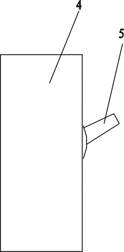
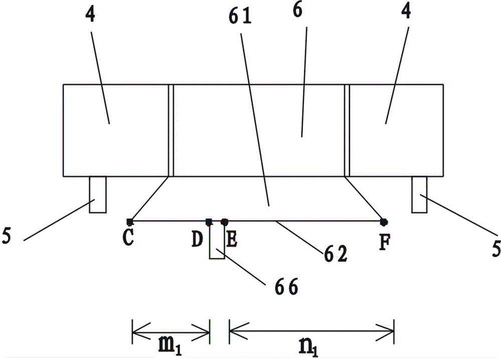
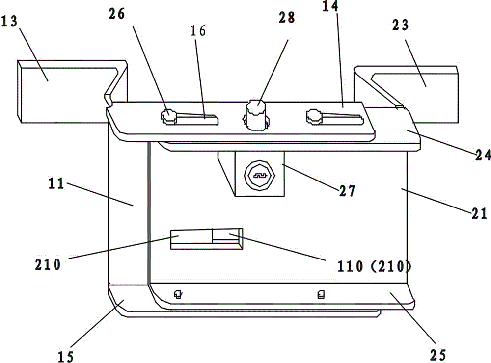
[0047] Figure 6 , Figure 7 , Figure 8 , Figure 9 , Figure 10 As shown, an equipment box door and an upstream double power supply circuit breaker interlock control mechanism, including an equipment box 7, the equipment box is provided with an equipment box door 71, the equipment box door 71 is provided with a door lock 72, and the door lock 72 is provided with a first lock Core 73 and key 74, the first lock core 73 is provided with the lock key restriction pull-out structure that restricts key 74 to be pulled out under unlocking state; There is a circuit breaker between them, and the two power supplies supply power to the equipment box through the circuit breaker respectively. The power supply relationship is as follows: Figure 6 indicated by the dotted arrow in the middle; Figure 7 , Figure 8 , Figure 10 As shown, a control box 6 is installed between the left and right circuit breakers 4, and each circuit breaker 4 is provided with a control handle 5 that can r...


PUM


Abstract

An equipment box door and upstream dual-power-circuit-breaker interlocking control mechanism comprises an equipment box. The upstream of the equipment box is connected with a main power source and a stand-by power source, and circuit breakers are arranged between the two power sources and the equipment box respectively. A control box is mounted between the left circuit breaker and the right circuit breaker, the control box protrudes forwards relative to the left circuit breaker and the right circuit breaker, and the protruding part of the control box is of an isosceles trapezoid shape with the front portion being large and the rear portion being small. A lock fastening piece is further included, the lock fastening piece comprises a left fastening piece and a right fastening piece, and the left fastening piece and the right fastening piece can be connected together in a left-right relative sliding mode. A left lock hole is formed in the center of an upper left eyebrow plate, and a right lock hole is formed in the center of an upper right eyebrow plate. The right fastening piece is provided with a second lock, the second lock is provided with a spring bolt and a second lock cylinder, only the same key is matched with the second lock cylinder and a first lock cylinder, and the spring bolt of the second lock is directed at the right lock hole. The equipment box door and upstream dual-power-circuit-breaker interlocking control mechanism is simple and convenient to operate, and single in element of a control link, when the equipment box is overhauled, the two circuit breakers can be guaranteed to be in a brake separating state, and the state can not be changed by a third person.

Description

technical field [0001] The invention belongs to the technical field of electrical equipment, and in particular relates to an interlocking control mechanism for an equipment box door and an upstream double power supply circuit breaker. Background technique [0002] When the equipment box is tested and overhauled, it must be ensured that the upstream power supply to it is disconnected to ensure the safety of the overhaul personnel. Generally, the equipment box is equipped with an equipment box door, and the equipment box door is equipped with a door lock. The door lock of the equipment box door is equipped with a lock cylinder, and the lock cylinder is equipped with a key. Only then can the door of the equipment box be opened for testing and maintenance. Generally, the lock core is provided with a key restricting extraction structure that restricts the key from being extracted in the unlocked state. The key restricting extraction structure is a known technology, which makes t...

Claims


Application Information

Patent Timeline
IPC IPC(8): H01H9/20H01H9/28
Inventor 吴汉榕蔡汉标陈炎亮吴晓生
Owner 广东正超电气有限公司
Why Eureka
Try Eureka