Adjacent cell handover method, equipment and system

A neighboring cell and device technology, applied in electrical components, wireless communication, etc., can solve problems such as low handover success rate

Active Publication Date: 2013-12-11
COMBA TELECOM SYST CHINA LTD
View PDF4 Cites 15 Cited by
  • Summary
  • Abstract
  • Description
  • Claims
  • Application Information

AI Technical Summary

Problems solved by technology

[0005] Embodiments of the present invention provide a method, device and system for handover of adjacent cells, which are u

Method used


Image

  • Adjacent cell handover method, equipment and system
  • Adjacent cell handover method, equipment and system
  • Adjacent cell handover method, equipment and system

Examples


Embodiment 1

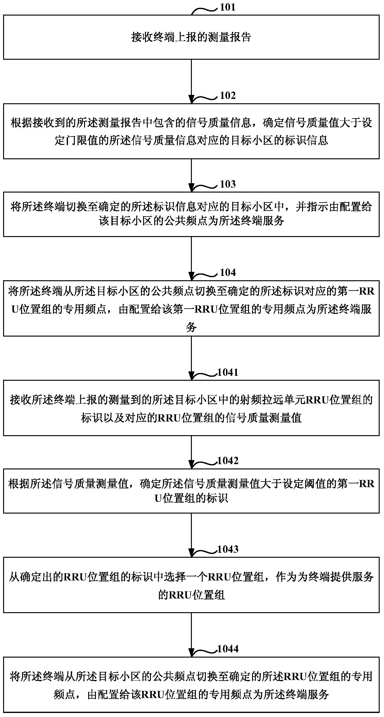
[0027] Such as figure 1 As shown, it is a flowchart of a method for handover of a neighboring cell in Embodiment 1 of the present invention, and the method includes:

[0028] Step 101: Receive a measurement report reported by a terminal.

[0029] Wherein, the measurement report includes identification information of at least one target cell adjacent to the current serving cell of the terminal and signal quality information of the target cell.

[0030] Specifically, in step 101, during the mobile process, the terminal firstly receives the neighboring cell configuration information broadcast by the current serving cell, wherein the neighboring cell configuration information includes the identification information of the neighboring cell and the common frequency point of the neighboring cell information.

[0031] Secondly, the terminal measures the signal quality of the neighboring cell according to the received configuration information of the neighboring cell.

[0032] Speci...

Embodiment 2

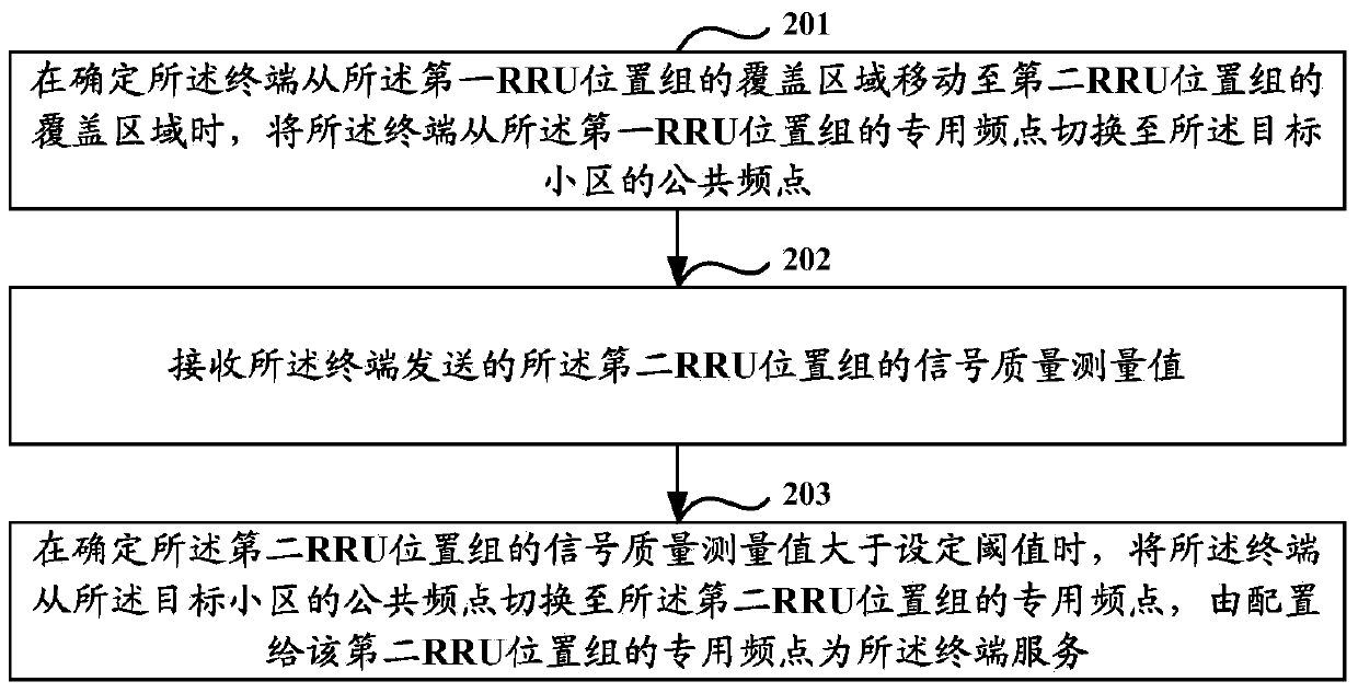
[0070] Such as figure 2 As shown in FIG. 2 , it is a flow chart of a method for handover of a neighboring cell according to Embodiment 2 of the present invention. Embodiment 2 of the present invention is an invention under the same concept as Embodiment 1 of the present invention, and is a method for switching between different RRU location groups of a target cell, the method comprising:

[0071] Step 201: When it is determined that the terminal moves from the coverage area of ​​the first RRU location group to the coverage area of ​​the second RRU location group, switch the terminal from the dedicated frequency point of the first RRU location group to the The public frequency point of the target cell.

[0072] Specifically, in step 201, first, when it is determined that the terminal moves from the coverage area of ​​the first RRU location group to the coverage area of ​​the second RRU location group, the first RRU location group acquires the The measured value of the uplink...

Embodiment 3

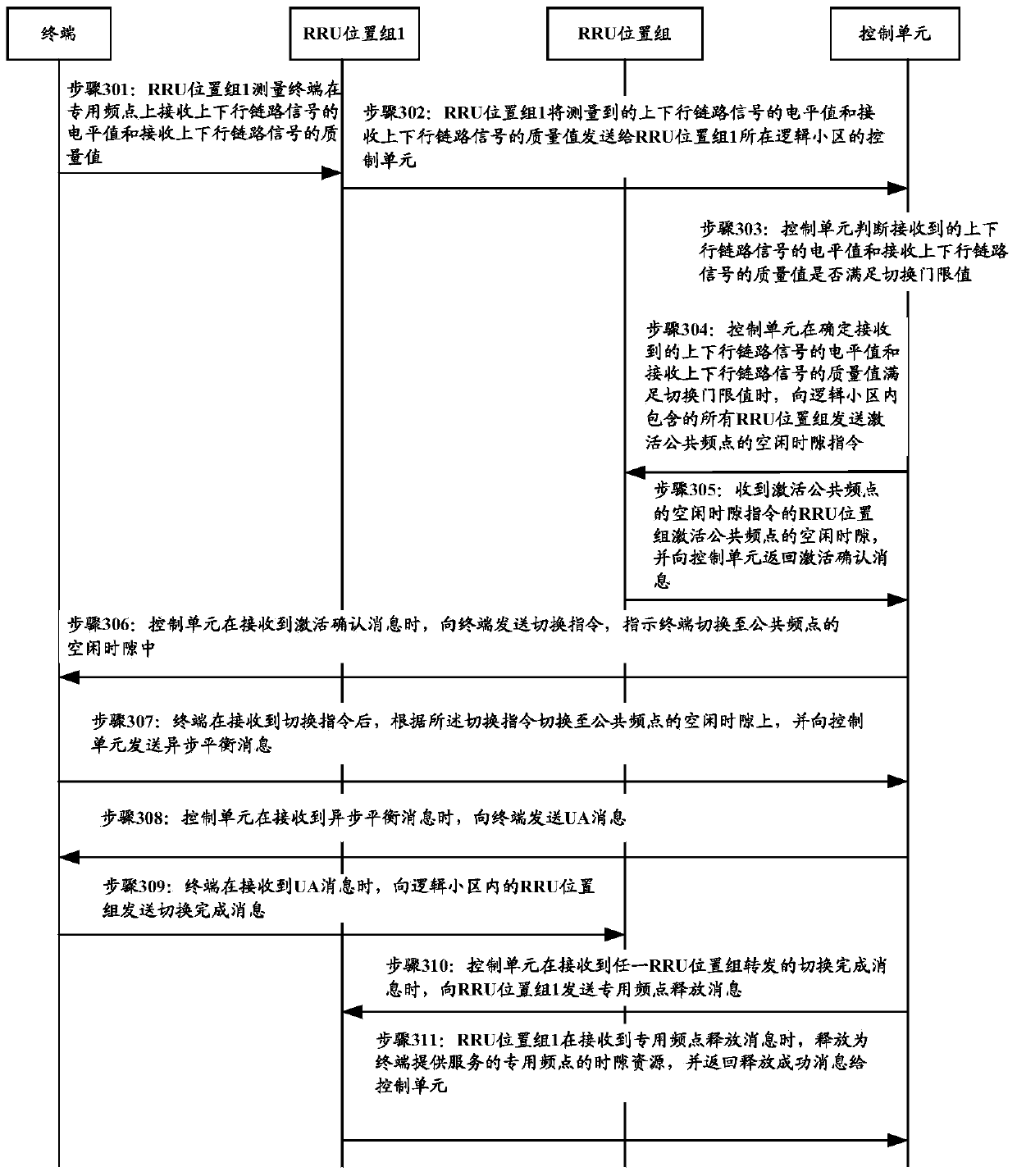
[0083] Such as image 3 As shown in FIG. 2 , it is a schematic flowchart of a method for handover of a neighboring cell according to Embodiment 3 of the present invention. Embodiment 3 of the present invention is described by taking the handover of the terminal from the dedicated frequency point of the currently accessed RRU position 1 to the public frequency point of the logical cell as an example. The methods include:

[0084] Step 301: RRU position group 1 measures the level value of the uplink and downlink signals received by the terminal on the dedicated frequency point and the quality value of the received uplink and downlink signals.

[0085] Preferably, when the RRU position group 1 measures the level value of the uplink and downlink signals received by the terminal on the dedicated frequency point and the quality value of the received uplink and downlink signals, since the position group adjacent to the RRU position group 1 maintains Pre-synchronization, and further...


PUM


Abstract

The invention discloses an adjacent cell handover method, equipment and a system. The method comprises the steps that after a terminal is handed over to a target cell, a public frequency point configured to the target cell serves the terminal and receives measured identification, of an RRU position group in the target cell, reported by the terminal, and a measured signal quality value of the corresponding RRU position group, the identification of the first RRU position group with the measured signal quality value larger than a set threshold value is determined according to the measured signal quality value, the terminal is handed over to a determined dedicated frequency point of the first RRU position group from the public frequency point of the target cell, the dedicated frequency point serves the terminal, and after the terminal is handed over to the target cell, the public frequency point of the target cell is utilized as a handover medium to execute the handover operation. Thus, the problem that handover fails when the terminal is directly handed over to a certain RRU position group is avoided, and the handover success rate of the terminal in the heterogeneous network system is improved.

Description

technical field [0001] The present invention relates to the field of wireless communication, in particular to a method, device and system based on handover of neighboring cells in a heterogeneous network. Background technique [0002] With the popularity of smart phones and tablet computers, the mobile Internet has been integrated into our lives, and people's demand for high-speed broadband services has promoted the rapid development of mobile communications. In order to improve the utilization rate of spectrum resources, the mobile communication network is developing from a macro cellular network to a micro cellular network, and to a network formed by mixing a macro cellular network and a micro cellular network. [0003] Due to the small coverage radius of the micro-cell network signal, multiple micro-cell networks are required for signal coverage in an area per unit area. The number is relatively large. When a terminal switches between a macro base station and a micro bas...

Claims


Application Information

Patent Timeline
IPC IPC(8): H04W36/30
Inventor 吴汉光刘逸豪
Owner COMBA TELECOM SYST CHINA LTD
Why Eureka
Try Eureka