
Device for turning over and transferring the patient

一种移位机、减速机的技术,应用在翻身移位机领域,能够解决升降行程受限、升降范围高、折板增加成本等问题,达到增加升降范围、增加升降行程的效果

Inactive Publication Date: 2013-12-18
王义龙
View PDF8 Cites 13 Cited by
  • Summary
  • Abstract
  • Description
  • Claims
  • Application Information

AI Technical Summary

Problems solved by technology

Due to the basic length of the mother shell, its lifting range is relatively high, which leads to the limitation of the lifting stroke, which fails to meet the actual needs
[0016] (3) The above-mentioned former patent uses a hanging net with a folded plate inside to hook the suspension rope to turn over, but the folded plate has the disadvantages of increased cost, bulkiness, hindrance, difficulty in folding and inconvenient cleaning
[0018] In summary, the above-mentioned types of care equipment for stroke patients, vegetative people or people who have been bedridden for a long time, although they all have their own functions, do not have the convenience of integrating one machine with multiple functions for taking care of patients
In addition to the high purchase cost, it also takes up space and fails to meet the overall needs of home patient rehabilitation and care

Method used


Image

  • Device for turning over and transferring the patient
  • Device for turning over and transferring the patient
  • Device for turning over and transferring the patient

Examples


Embodiment Construction

[0101] In order to make the structural features of the present invention and the achieved effects have a further understanding and recognition, preferred embodiments and detailed descriptions are specially used, which are described as follows:

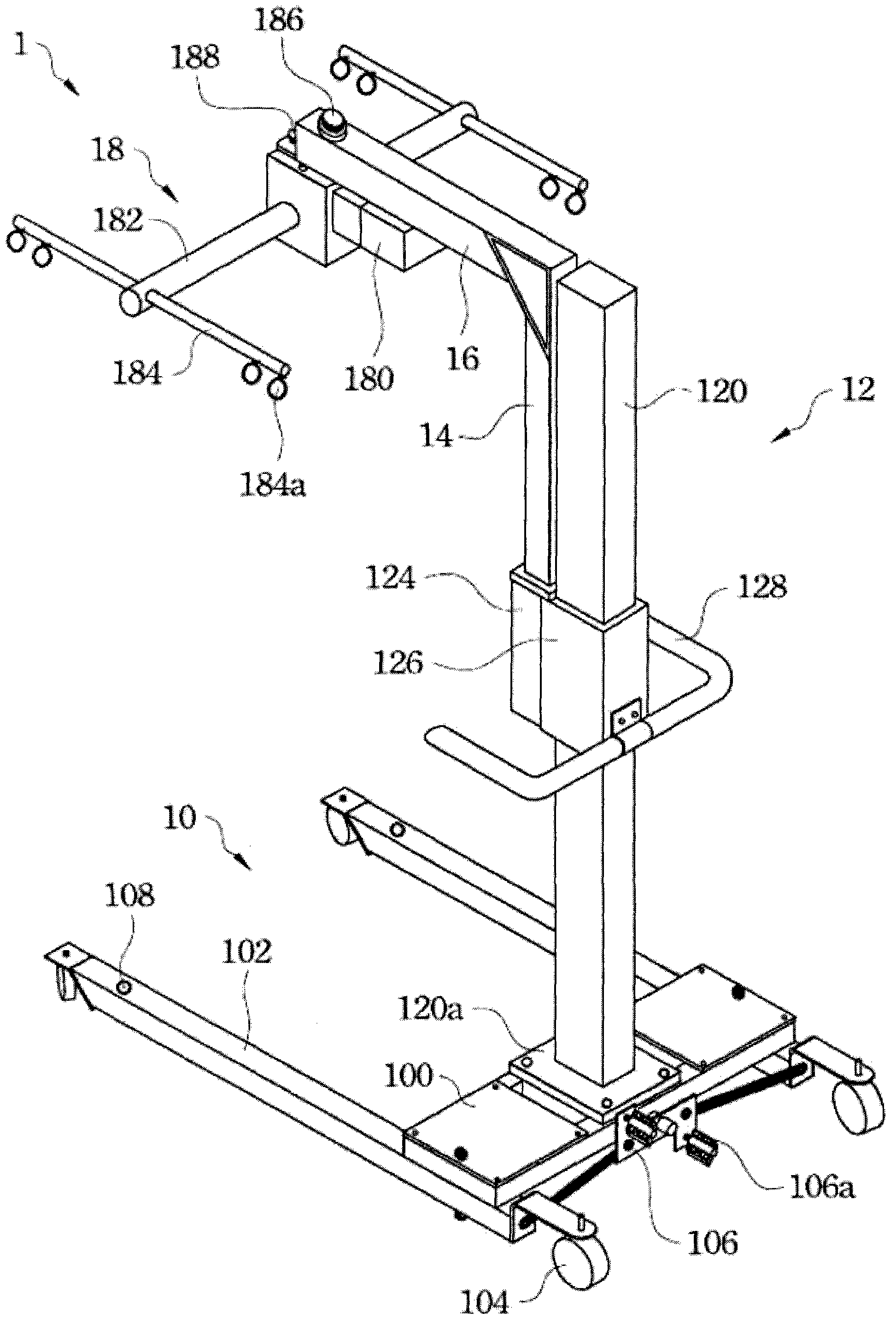
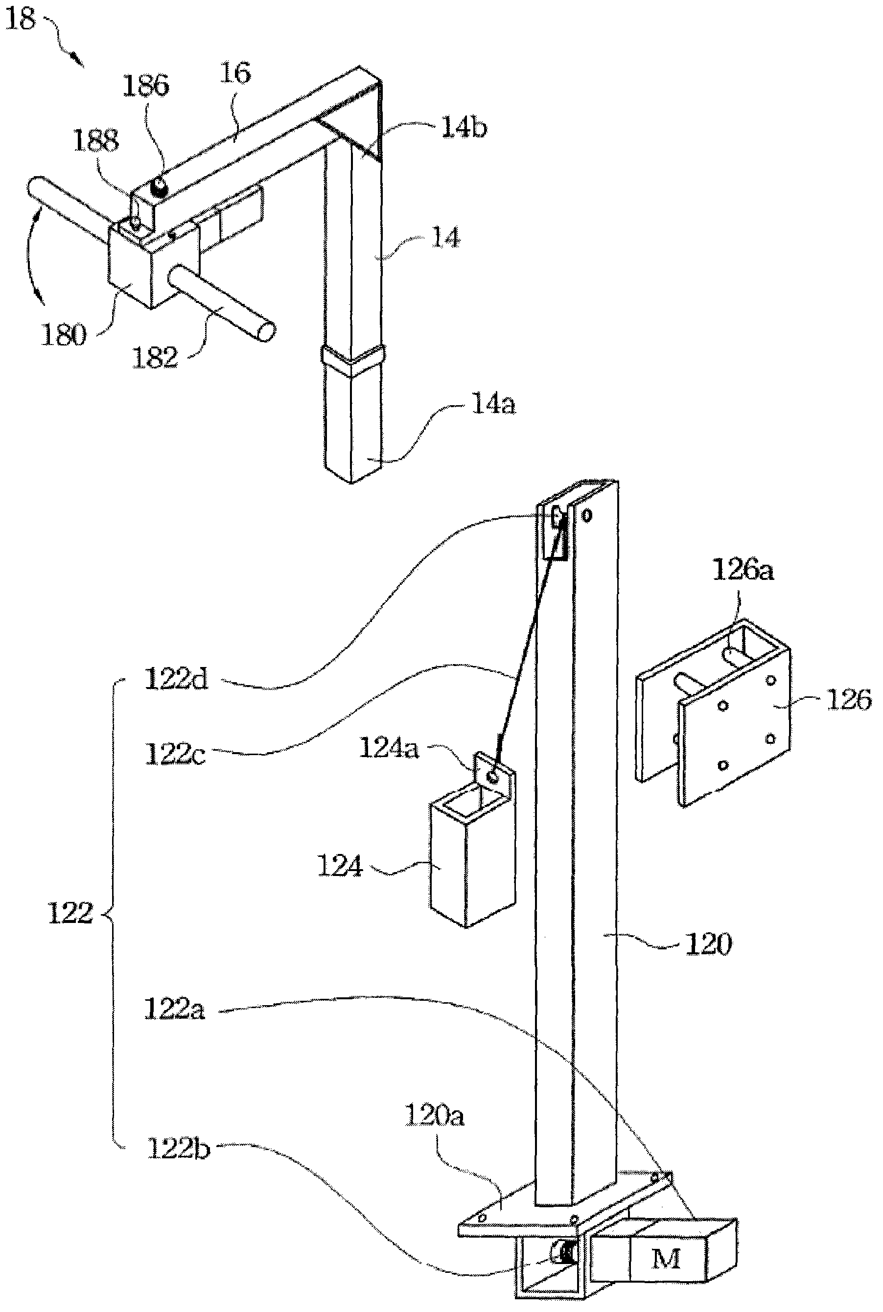
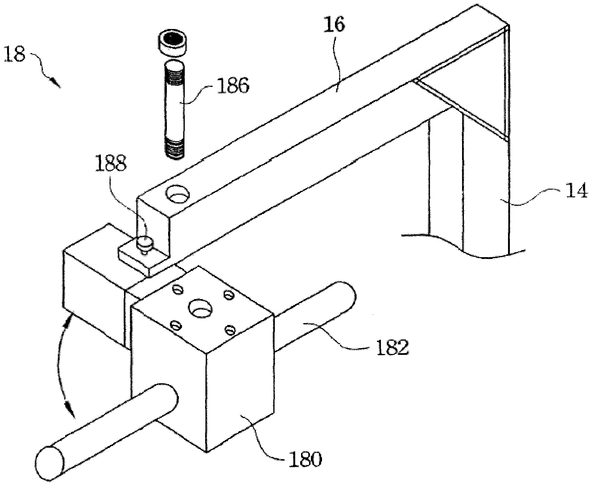
[0102] Please refer to Figure 1A , Figure 1B as well as Figure 1C . Figure 1A It is a three-dimensional assembled view of the turning and lifting machine 1 according to an embodiment of the present invention. Figure 1B for illustration Figure 1A A partial exploded view of the turning lift 1 in . Figure 1C for illustration Figure 1A A partial exploded view of the turning lift 1 in .

[0103] like Figure 1A and Figure 1B As shown, in this embodiment, the turning machine 1 includes a base 10 , a lifting mechanism 12 , an extension arm 14 , a cantilever beam 16 and a turning drive device 18 . The base 10 of the turning machine 1 includes a base box 100 , a base beam 102 , a bottom wheel 104 , a beam spreading mechanism 106 , ...


PUM


Abstract

A device for turning over and transferring the patient comprises a base, a lifting mechanism, an extension arm, a cantilever beam, and a turn driving device. The lifting mechanism comprises a lifting post and a lift driving device. The lifting post is fixed to the base; the lift driving device is fixed to the lifting post. The extension arm has a first end and a second end. The lift driving device is operatively connected to the first end for driving the extension arm to move up and down along the lifting post. The cantilever beam is connected to the second end and extending away from the lifting post. The turn driving device comprises a motor reducer, a revolutionary shaft, and two turning shafts. The motor reducer is connected pivotally to the cantilever beam. The revolutionary shaft is connected to the motor reducer; the revolutionary shaft rotates when it is driven by the motor reducer. The two turning shafts are fixed to both ends of revolutionary shaft, respectively, and turned relative to the motor reducer as the revolutionary shaft rotates.

Description

technical field [0001] The present invention relates to a turning and lifting machine, in particular to a medical auxiliary equipment used for nursing and rehabilitation. Background technique [0002] In the age of aging, many stroke patients, vegetative people or people who are bedridden for a long time, their bodies often degenerate rapidly due to lack of activity, or lack of turning over leads to bedsores, so they must rely on nursing staff and support equipment for daily care . Long-term care of bedridden patients is exhausting and heavy work. In order to improve the care ability of bedridden patients and reduce the labor burden of nursing staff, there is an urgent need for convenient and labor-saving nursing rehabilitation equipment. [0003] At present, the nursing and rehabilitation equipment used to care for bedridden patients on the market includes: [0004] 1. Turning bed: it has a single purpose for bedridden patients to turn over. [0005] 2. Air mattress: It ...

Claims


Application Information

Patent Timeline
Patent Type & Authority Applications(China)
IPC IPC(8): A61G7/057A61G7/14
CPCA61G7/1003A61G7/001A61G7/1019A61G7/1046A61G7/1051A61G7/1055A61G7/1067
Inventor 王义龙
Owner 王义龙
Learn More