Automatic tool changing device
An automatic tool changing and detection device technology, applied in the field of tool magazines, can solve the problems of high processing, assembly technology, tool recognition, unstable tool selection, high failure rate of machine tools, etc., achieve beautiful matching, improve reliability and production cycle , The effect of simplifying the tool magazine structure
Inactive Publication Date: 2013-12-18
JIANGSU SHINRI HEAVY IND SCI & TECH
View PDF6 Cites 3 Cited by
- Summary
- Abstract
- Description
- Claims
- Application Information
AI Technical Summary
Problems solved by technology
At present, the repeated positioning accuracy of domestic machine tool magazines is low; the recognition and selection of tools are unstable; the failure rate of cooperation with machine tools is high; and high processing and assembly processes are required.
Method used
View moreImage
Smart ImageViewing Examples
Examples
Embodiment Construction
Login to View More PUM
 Abstract
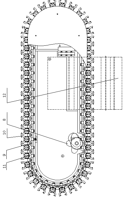
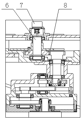
The invention relates to the technical field of automatic machine tools, in particular to an automatic tool changing device. An upper guide rail body and a lower guide rail body are fixedly arranged on an upright and are of an upper-lower connection structure, chain knots, toolholder bodies and chain links are sequentially connected and placed in the upper guide rail body and the lower guide rail body, the chain links are fixed on the upper guide rail body and the lower guide rail body, the chain knots and the toolholder bodies are mounted and fixed on the chain links, a chain wheel mounting shaft is arranged on the upper guide rail body and the lower guide rail body, a chain wheel is connected on the chain wheel mounting shaft, a servo motor and a speed reducing mechanism are fixedly connected on the upper guide rail body and the lower guide rail body, the speed reducing mechanism is connected with the chain wheel to drive the same, and a tool-changing detection device is arranged at the edge of the upper guide rail body. Reliability of a tool magazine is greatly improved, production cycle is greatly prolonged greatly, and tool changing of the automatic tool changing device is completed through matching of the tool magazine and a spindle. The tool magazine is fixed and the spindle moves for tool changing, so that moving inertia of the tool magazine is reduced, the structure of the tool magazine is simplified, and tool changing control is simple and reliable.
Description
technical field The invention relates to a tool magazine, in particular to an automatic tool changing device. Background technique At present, the repeated positioning accuracy of domestic machine tool magazines is low; tool recognition and tool selection are unstable; the failure rate of cooperation with machine tools is high; and high processing and assembly processes are required. Contents of the invention In order to solve the above technical problems, an automatic tool changing device is provided. In order to overcome the defects in the background technology, the technical solution adopted by the present invention to solve the technical problems is: the automatic tool changer includes a column, and the column is fixed with an upper guide rail body and a lower guide rail body, and the upper guide rail body and the lower guide rail The body is connected up and down. The upper rail body and the lower rail body are sequentially connected to place links, toolholders and...
Claims
Login to View More Application Information
Patent Timeline
 Patent Type & Authority Applications(China)
IPC IPC(8): B23Q3/155
Inventor 张秀明赵志惠黄加欣王明
Owner JIANGSU SHINRI HEAVY IND SCI & TECH
Features
- R&D
- Intellectual Property
- Life Sciences
- Materials
- Tech Scout
- Unparalleled Data Quality
- Higher Quality Content
- 60% Fewer Hallucinations
Learn More Browse by: Latest US Patents, China's latest patents, Technical Efficacy Thesaurus, Application Domain, Technology Topic, Popular Technical Reports.
© 2025 PatSnap. All rights reserved.Legal|Privacy policy|Modern Slavery Act Transparency Statement|Sitemap|About US| Contact US: help@patsnap.com


