
a wiper mechanism

A wiper and body technology, applied in the field of vehicle parts, can solve the problems of wiper mechanism failure and easy occurrence of slippage, and achieve the effects of accurate placement, beautiful coordination, and avoidance of edging

Active Publication Date: 2017-08-22
BYD CO LTD
View PDF6 Cites 0 Cited by
  • Summary
  • Abstract
  • Description
  • Claims
  • Application Information

AI Technical Summary

Problems solved by technology

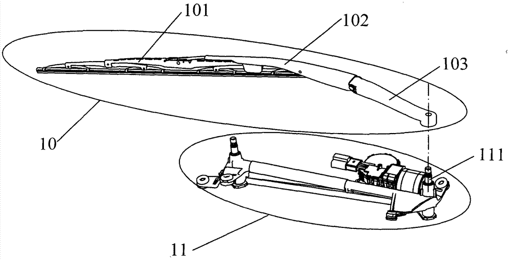
At present, the usual way of connecting the output shaft 111 and the scraper arm seat 103 is to match the splines on the hole shafts of the two, and then fasten the output shaft 111 and the scraper arm seat 103 through bolts and nuts, but this connection method The mating surface between the wiper arm seat 103 and the output shaft 111 is prone to slippage, so that the output shaft 111 cannot drive the wiper arm assembly 10 to swing, resulting in failure of the wiper mechanism

Method used


Image

  • a wiper mechanism
  • a wiper mechanism
  • a wiper mechanism

Examples


Embodiment Construction

[0029] In order to make the technical problems, technical solutions and beneficial effects solved by the present invention clearer, the present invention will be further described in detail below in conjunction with the accompanying drawings and embodiments. It should be understood that the specific embodiments described here are only used to explain the present invention, not to limit the present invention.

[0030] In describing the present invention, it should be understood that the terms "center", "longitudinal", "transverse", "length", "width", "thickness", "upper", "lower", "front", " Back", "Left", "Right", "Vertical", "Level", "Top", "Bottom", "Inside", "Outside", "Clockwise", "Counterclockwise", etc. or The positional relationship is based on the orientation or positional relationship shown in the drawings, which is only for the convenience of describing the present invention and simplifying the description, rather than indicating or implying that the referred device ...


PUM


Abstract

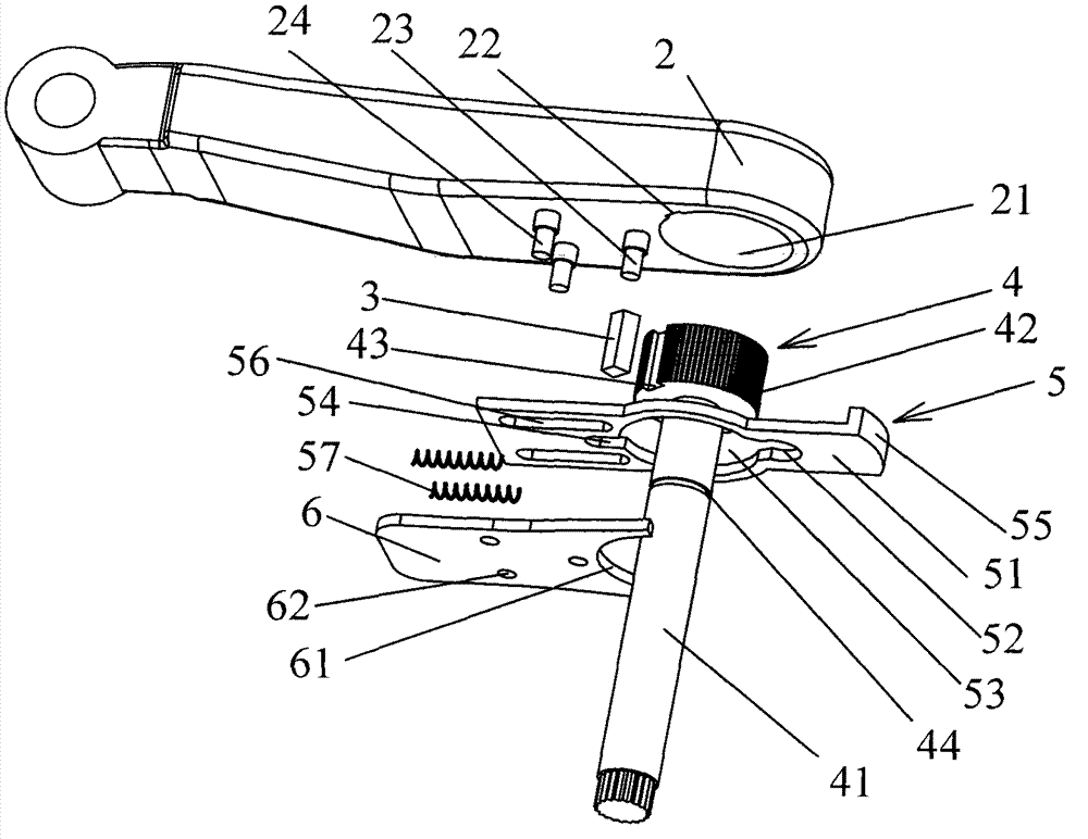
The invention provides a wiper mechanism. The wiper mechanism includes a wiper arm seat base, a fitting and an output shaft. The output shaft includes a shaft body, a shaft shoulder arranged at one end of the shaft body, and a The bottom surface of one end of the base body of the scraper arm base is provided with a blind hole that fits with the shaft shoulder clearance, the side wall of the blind hole is provided with a keyway, and the fitting is embedded in the groove formed by the keyway. In the cavity, the wiper mechanism further includes a locking piece for preventing the matching piece from being separated from the cavity, and the locking piece can be fixedly connected to the base body of the wiper arm seat. The output shaft in the wiper mechanism can provide a stable and reliable force to the wiper arm assembly, so as to avoid failure of the wiper mechanism.

Description

technical field [0001] The invention relates to vehicle component technology, in particular to a wiper mechanism. Background technique [0002] In the existing technology, such as figure 1 As shown, the wiper mechanism mainly includes two parts: the wiper arm assembly 10 and the motor linkage bracket assembly 11, and the wiper arm assembly 10 includes the wiper blade assembly 101, the wiper arm 102 and the wiper arm seat 103 connected in sequence, the motor The connecting rod bracket assembly 11 includes an output shaft 111 , which is connected to the scraper arm base 103 to drive the scraper arm assembly 10 to swing. At present, the usual way of connecting the output shaft 111 and the scraper arm seat 103 is to match the splines on the hole shafts of the two, and then fasten the output shaft 111 and the scraper arm seat 103 through bolts and nuts, but this connection method The mating surface between the wiper arm base 103 and the output shaft 111 is prone to wire slippin...

Claims


Application Information

Patent Timeline
Patent Type & Authority Patents(China)
IPC IPC(8): B60S1/34
Inventor 龙宪阁李志彬马经荣
Owner BYD CO LTD
Learn More