Check patentability & draft patents in minutes with Patsnap Eureka AI!

Novel despooling device

A pay-off device, a new type of technology, applied in the field of pay-off devices, can solve the problems of affecting work efficiency, high price, laborious aluminum core wire, etc., and achieve the effect of improving work efficiency, good mechanical stability and improving reliability

Active Publication Date: 2013-12-18
STATE GRID CORP OF CHINA +3
View PDF5 Cites 12 Cited by
  • Summary
  • Abstract
  • Description
  • Claims
  • Application Information

AI Technical Summary

Problems solved by technology

[0002] In the pay-off operation, there is a special pay-off device for overhead lines. The pay-off device is large in size, inconvenient to carry, heavy in weight, at least over 36KG, and expensive. In terms of work requirements; when installing the household line, you only have to slowly turn the wire with your arm, and it feels very difficult to continuously rotate the aluminum core wire of more than 35 square meters, let alone the copper core of the same type The line is broken, the labor intensity is high, which greatly affects the work efficiency

Method used


Image

  • Novel despooling device
  • Novel despooling device
  • Novel despooling device

Examples


Embodiment 1

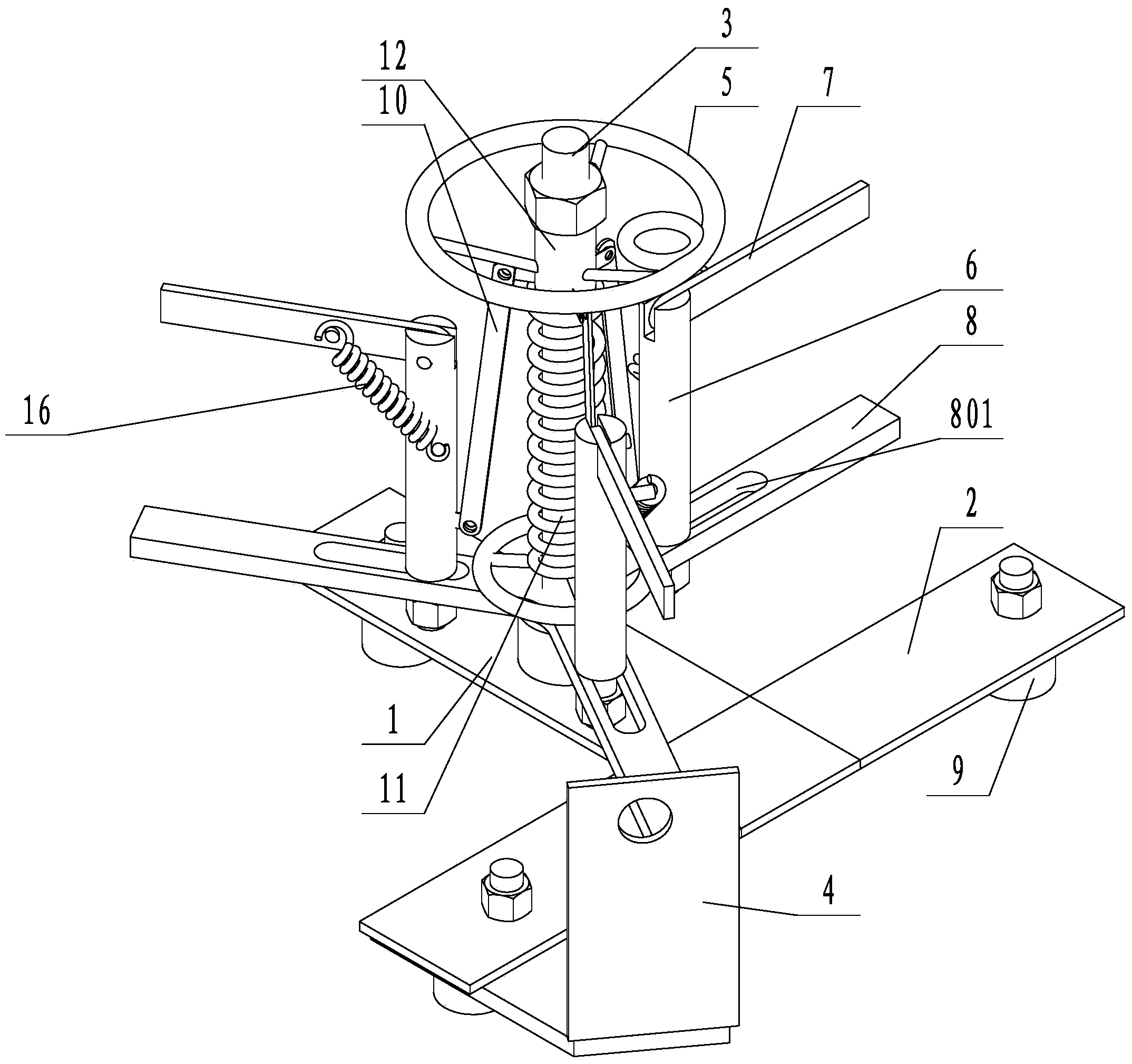
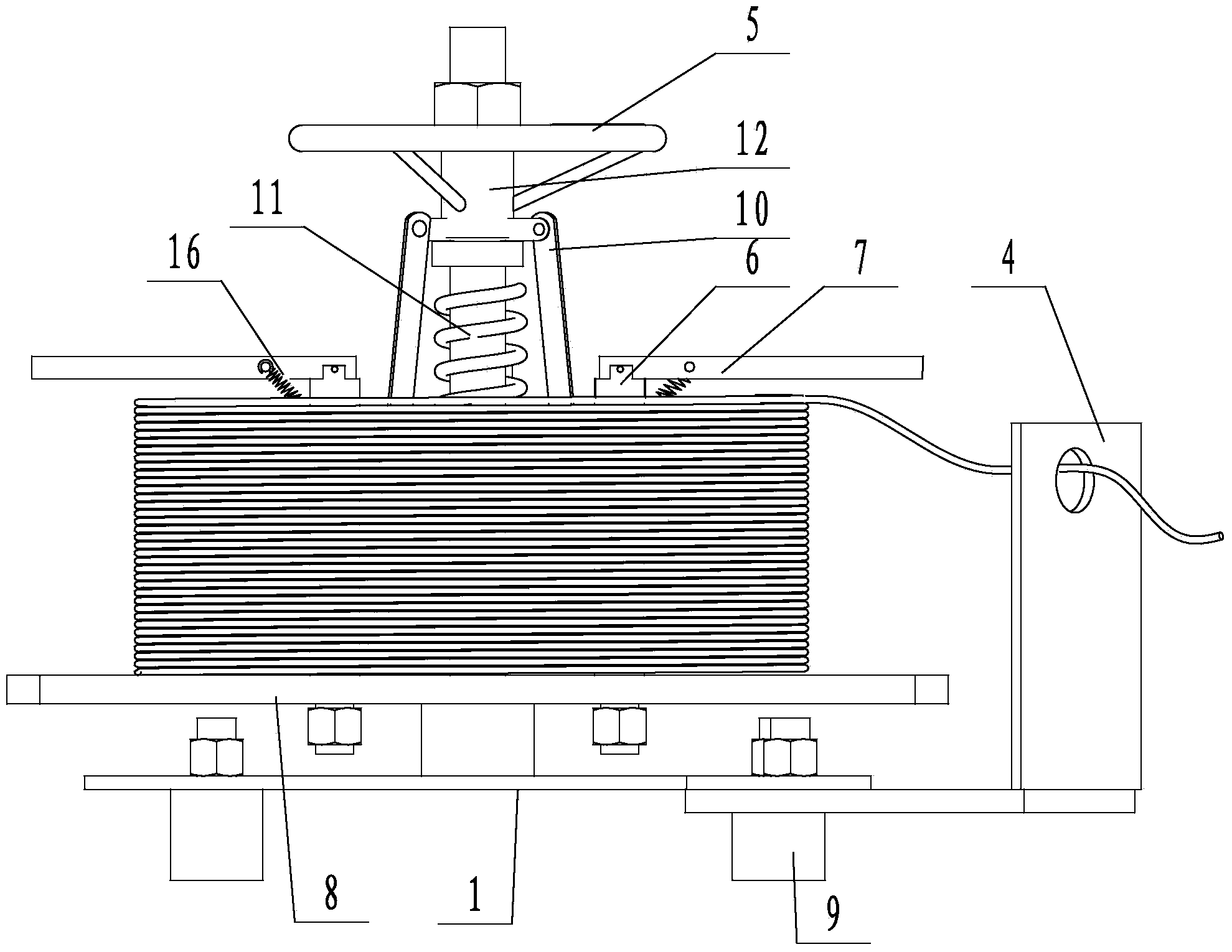
[0029] like figure 1 As shown, the present invention includes a base, a vertical shaft 3 arranged in the middle of the base, a guide frame 4 arranged on the base, a turntable connected in rotation with the vertical shaft 3, a hand plate 5 arranged above the turntable, and a plurality of evenly arranged spacers on the circumference. Frame; the middle part of the guide frame 4 is provided with a threading hole; the limit frame is detachably connected vertically on the turntable, and the turntable is provided with a plurality of waist-shaped grooves 801, and the limit frame can The groove 801 moves radially to adjust the radial size to meet the multi-standard reels; the limit frame includes a vertical rod 6 and a height limit rod 7, and the lower end of the vertical rod 6 is provided with external threads, and the lower end of the vertical rod 6 It is inserted into the waist-shaped groove and fixedly connected to the turntable through nuts; the vertical rod 6 is movably connected...

Embodiment 2

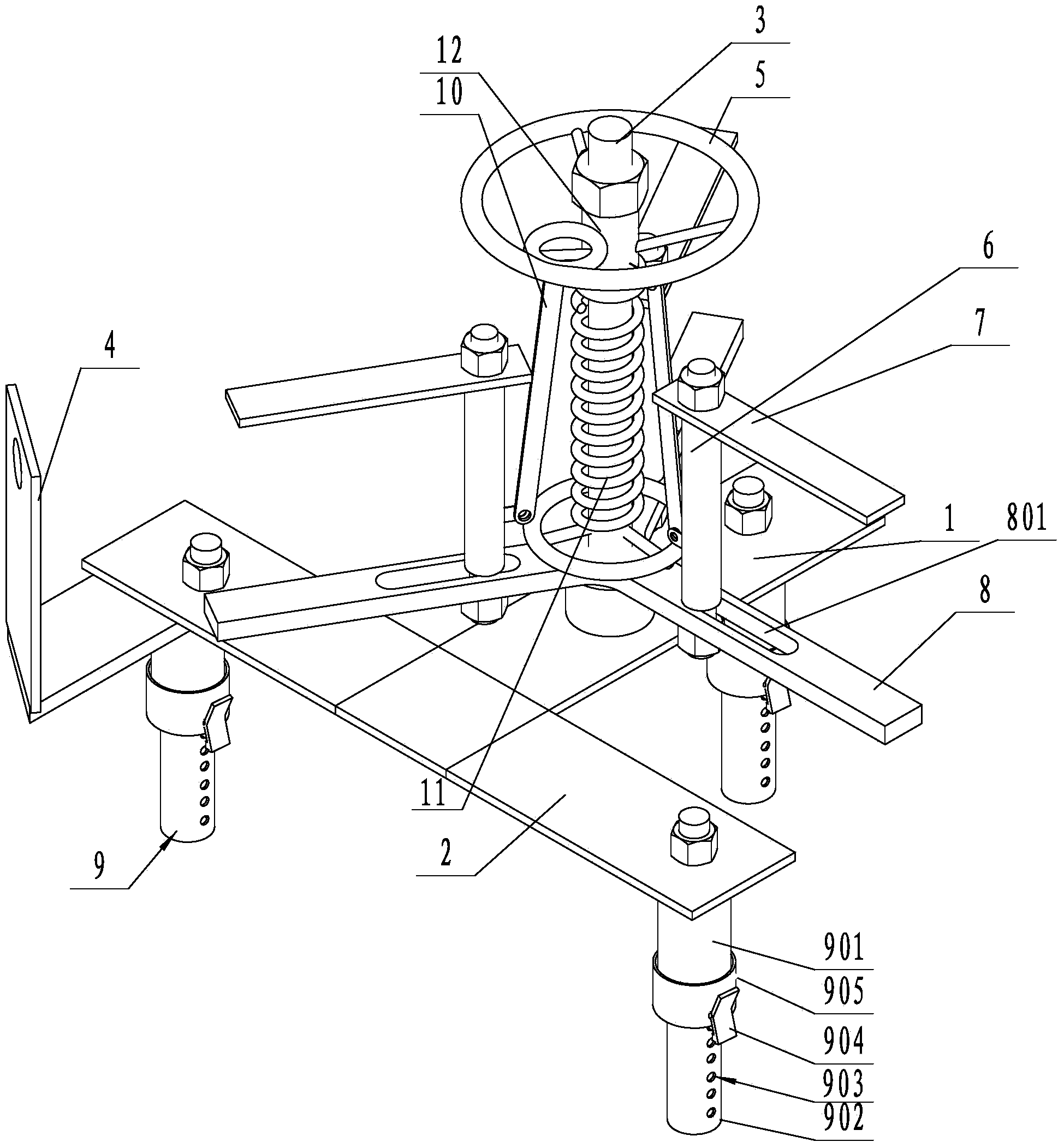
[0033] To adapt to different ground, especially slopes, or other uneven ground. like image 3 As shown, the difference from the first embodiment is that three height-adjustable legs 9 are provided under the base. The adjustable supporting foot 9 can be in the form of a screw, and the length of the screw can be determined by the rotation of the screw, or the adjustment of the length can be realized by connecting the sleeves one by one. In this embodiment, the support foot 9 includes an outer cylinder 901, an inner cylinder 902, and a positioning mechanism provided on the outer cylinder 901. The outer cylinder 901 is fixedly connected to the turntable, and the outer cylinder 901 is overlaid on the inner cylinder 902. , the outer cylinder 901 and the inner cylinder 902 have a clearance fit, the inner wall of the outer cylinder 901 is provided with at least one axial guide groove, the outer wall of the inner cylinder 902 is provided with a guide bar matching the guide groove of t...

Embodiment 3

[0035] To accommodate different reel sizes, such as Figure 4 As shown, the difference from Embodiment 1 is that each rotating bar is provided with an elongated bar 17 that can move on the rotating bar to change the size of the turntable, and the described elongated bar 17 and the rotating bar 8 are fixed by screws . The cross-section of the elongated bar 17 is "n"; the elongated bar 17 is outsourced on the rotating bar 8; the elongated bar 17 and the rotating bar 8 are provided with a plurality of through holes, and screws are inserted in the through holes to make the elongated bar 17 is fixed on the turning bar 8.


PUM


Abstract

The invention discloses a novel despooling device, which relates to a despooling device. At present, the despooling device is large in size, heavy in weight, expensive in cost and single in type of a suited guide line. The novel despooling device comprises a base, a vertical shaft, a guide frame, a rotating disk, a hand disk and multiple limiting frames, wherein the vertical shaft is arranged at the middle part of the base, the guide frame is arranged on the base, the rotating disk is rotationally connected with the vertical shaft, the hand disk is arranged above the rotating disk, and the multiple limiting frames are circumferentially and uniformly arranged; the middle part of the guide frame is provided with a threading hole; the limiting frames are detachably and vertically connected to the rotating disk, the rotating disk is provided with multiple waist-shaped grooves, and the limiting frames can move along radial directions of the waist-shaped grooves so that the radial sizes can be adjusted for satisfying coil disks in various types; the limiting frames comprise vertical rods and height limiting rods, and the lower ends of the vertical rods are provided with external threads, inserted in the waist-shaped grooves and fixedly connected to the rotating disk through nuts; the vertical rods are movably connected with the height limiting rods. Due to the technical scheme, the novel despooling device disclosed by the invention is small and light, simple in structure, convenient to operate, convenient to carry and high in working efficiency.

Description

technical field [0001] The invention relates to a wire payoff. Background technique [0002] In the pay-off operation, there is a special pay-off device for overhead lines. The pay-off device is large in size, inconvenient to carry, heavy in weight, at least over 36KG, and expensive. In terms of work requirements; when installing the household line, you only have to slowly turn the wire with your arm, and it feels very difficult to continuously rotate the aluminum core wire of more than 35 square meters, let alone the copper core of the same type The line is broken, and the labor intensity is high, which greatly affects work efficiency. Contents of the invention [0003] The technical problem to be solved and the technical task proposed by the present invention are to perfect and improve the existing technical solutions and provide a new type of pay-off device to achieve the purpose of portability and low cost. For this reason, the present invention takes the following t...

Claims


Application Information

Patent Timeline
IPC IPC(8): B65H75/38B65H75/44
Inventor 徐旭春俞永江董寒松董国成俞自江刘和秋刘国平刘能
Owner STATE GRID CORP OF CHINA
Features
  • R&D
  • Intellectual Property
  • Life Sciences
  • Materials
  • Tech Scout
  • Unparalleled Data Quality
  • Higher Quality Content
  • 60% Fewer Hallucinations
Learn More