Weighing-sensor-free self-adaption starting torque compensation method of elevator permanent-magnet dragging guiding system
A technology of load cell and traction system, which is applied to elevators, lifts, transportation and packaging in buildings, etc., can solve the problems of reduced reliability and increased cost of elevator systems.
- Summary
- Abstract
- Description
- Claims
- Application Information
AI Technical Summary
Problems solved by technology
Method used
Image
Examples
specific Embodiment approach 1
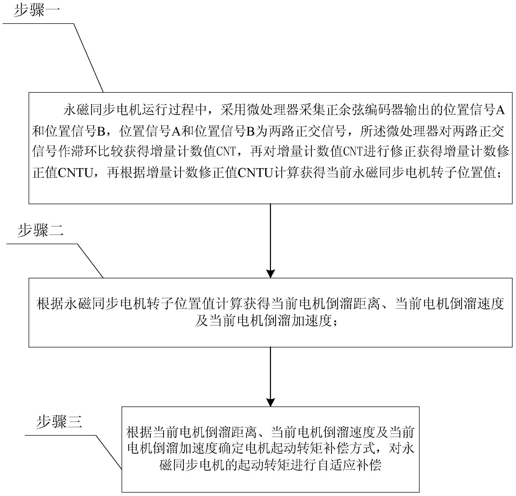
[0097] Specific implementation mode one: the following combination figure 1 This embodiment is described. The elevator permanent magnet traction system in this embodiment does not have a weighing sensor adaptive starting torque compensation method. The permanent magnet traction system uses a permanent magnet synchronous motor as the traction machine. The permanent magnet synchronous motor Using a sine-cosine encoder as a position sensor, it includes the following steps:
[0098] Step 1: During the operation of the permanent magnet synchronous motor, a microprocessor is used to collect the position signal A and the position signal B output by the sine-cosine encoder, the position signal A and the position signal B are two orthogonal signals, and the microprocessor The two-way quadrature signal is compared with hysteresis to obtain the incremental count value CNT, and then the incremental count value CNT is corrected to obtain the incremental count correction value CNTU, and the...
specific Embodiment approach 2
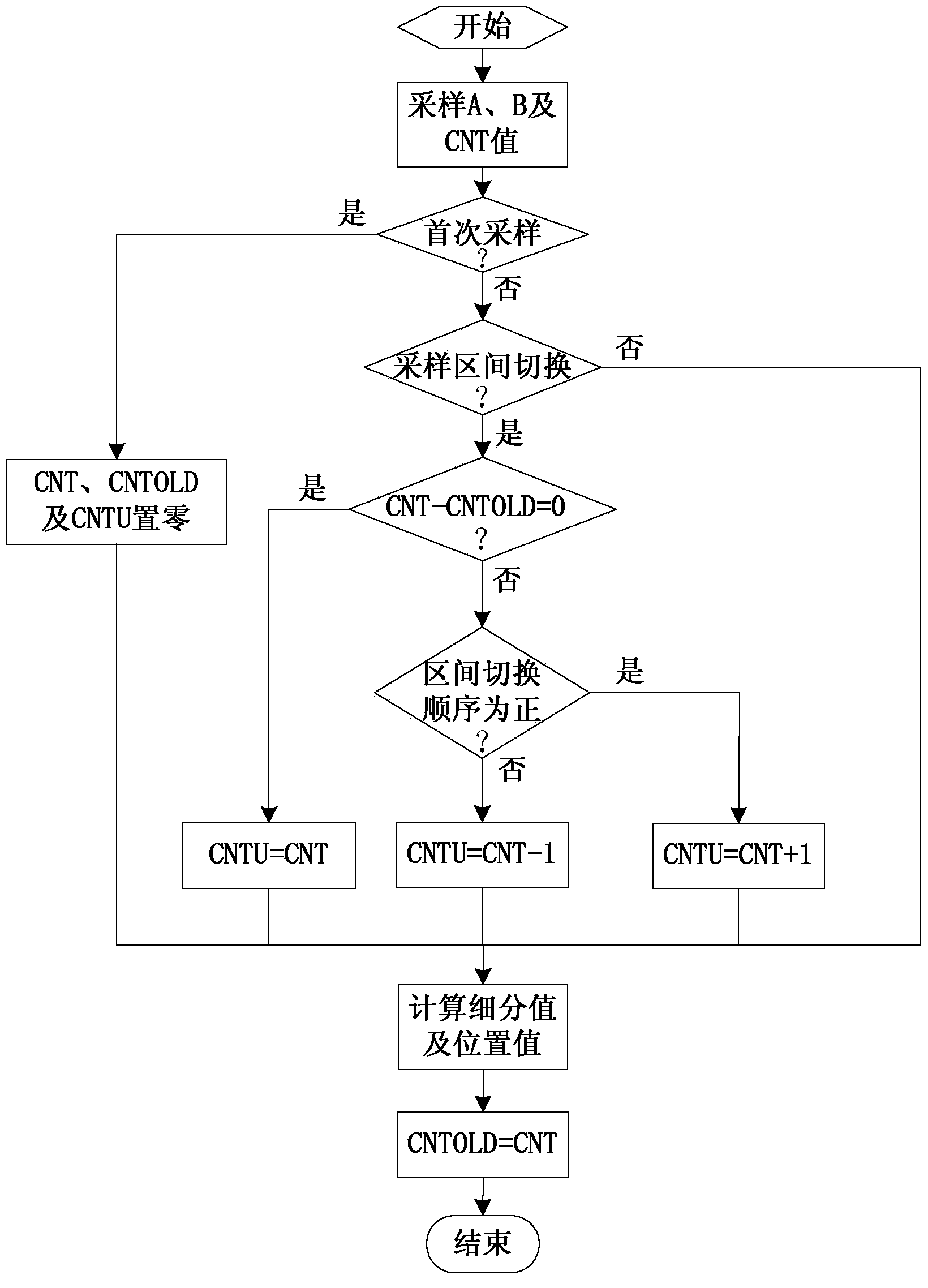
[0101] Specific implementation mode two: the following combination image 3 Describe this embodiment, this embodiment will further explain the first embodiment, the specific method of correcting the incremental count value CNT to obtain the incremental count correction value CNTU in step 1 is as follows:
[0102] When the microprocessor collects the position signal A and position signal B output by the sine-cosine encoder for the first time, it first sets the incremental count value CNT, the incremental count correction value CNTU and the incremental count value CNTOLD of the previous sampling period to zero; then Position signal A and position signal B do arc tangent calculation to obtain subdivision value θ div , and then according to the subdivision value θ div Calculate the permanent magnet synchronous motor rotor position value θ with the incremental count correction value CNTU; assign the incremental count value CNT to the incremental count value CNTOLD of the previous ...
specific Embodiment approach 3
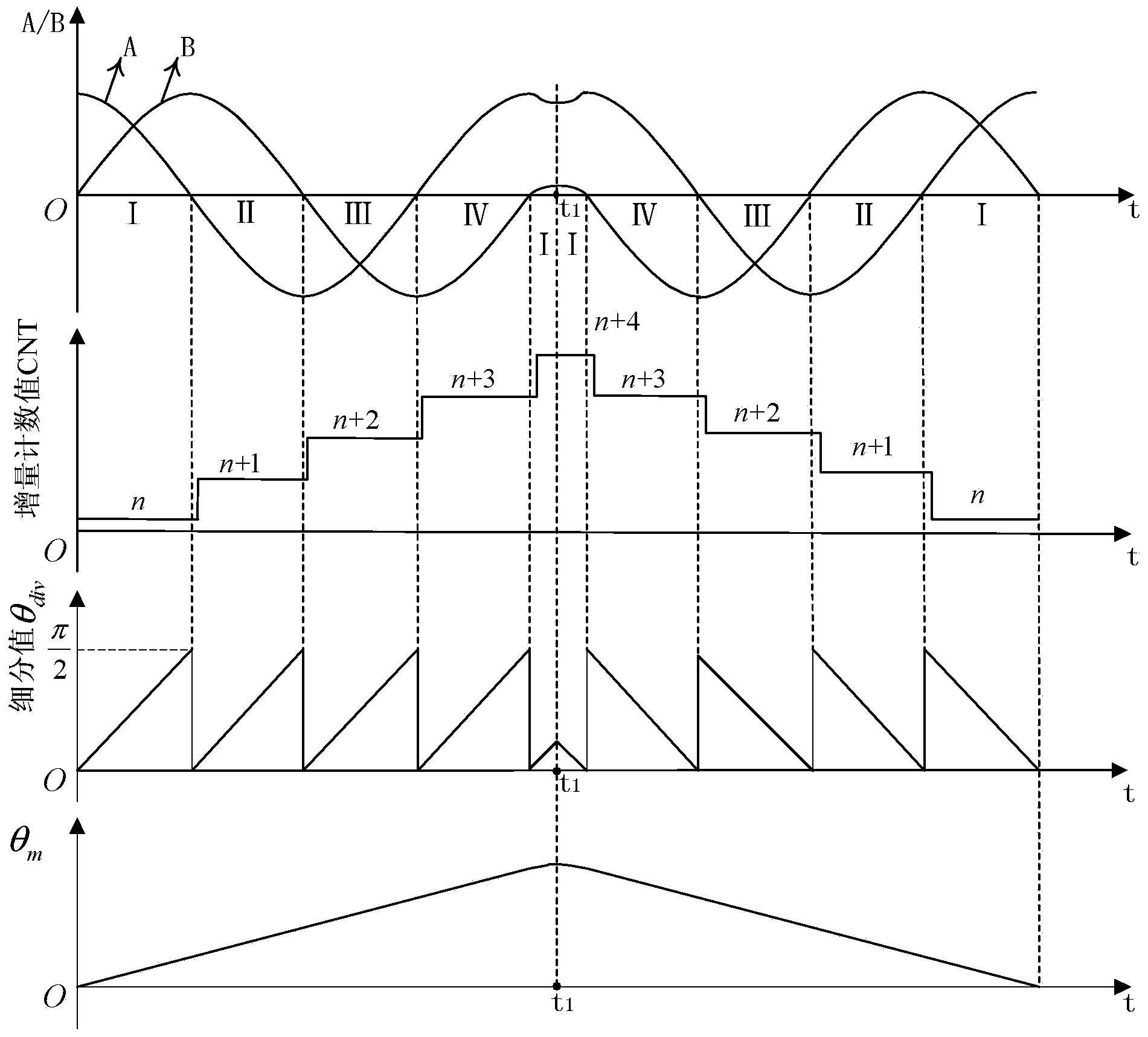
[0111] Specific implementation mode three: the following combination figure 2 Describe this embodiment mode, this embodiment mode is further described to embodiment mode 2, and the specific method of judging the steering of permanent magnet synchronous motor is:
[0112] The position signal A and the position signal B output by the sine-cosine encoder are periodic orthogonal signals, which are divided into four intervals I, II, III and IV in sequence. In the interval I, the position signal A is positive, and the position signal B is positive; in interval II, position signal A is negative and position signal B is positive; in interval III, position signal A is negative and position signal B is negative; in interval IV, position signal A is positive and position Signal B is negative;
[0113] When the interval switching sequence of position signal A and position signal B output by the sine-cosine encoder is: Ⅰ→Ⅱ, Ⅱ→Ⅲ, Ⅲ→IV or Ⅳ→Ⅰ, it is determined that the permanent magnet syn...
PUM
 Abstract
Description
Claims
Application Information
 - R&D
- Intellectual Property
- Life Sciences
- Materials
- Tech Scout
- Unparalleled Data Quality
- Higher Quality Content
- 60% Fewer Hallucinations
Browse by: Latest US Patents, China's latest patents, Technical Efficacy Thesaurus, Application Domain, Technology Topic, Popular Technical Reports.
© 2025 PatSnap. All rights reserved.Legal|Privacy policy|Modern Slavery Act Transparency Statement|Sitemap|About US| Contact US: help@patsnap.com


