Exhaust manifold circulation area self-regulation type engine system

An engine system and exhaust branch pipe technology, which is applied in combustion engines, machines/engines, internal combustion piston engines, etc., can solve the problems of complex structure of the supercharging system, and achieve the effect of simple structure and reasonable design.

Inactive Publication Date: 2013-12-18
SHANGHAI JIAO TONG UNIV
View PDF6 Cites 3 Cited by
  • Summary
  • Abstract
  • Description
  • Claims
  • Application Information

AI Technical Summary

Problems solved by technology

[0003] After searching the existing technical literature, it is found that Chinese patent number ZL201020532937.0, patent name: turbocharger device with variable exhaust pipe outlet area, this patent technology provides a device with continuously variable exhaust pipe outlet area , can better take into account the high and low speed conditions of the engine; but the change of the outlet area of ​​the exhaust pipe is realized by the rotation of the rotary handle, which requires adding a special control mechanism to control the rotation of the rotary handle, so that Make the supercharging system structure more complicated

Method used


Image

  • Exhaust manifold circulation area self-regulation type engine system
  • Exhaust manifold circulation area self-regulation type engine system
  • Exhaust manifold circulation area self-regulation type engine system

Examples


Embodiment

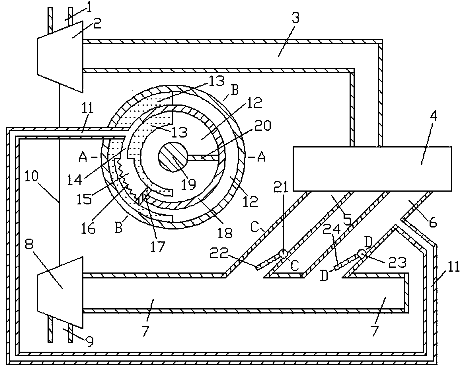
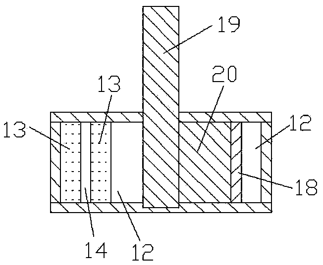
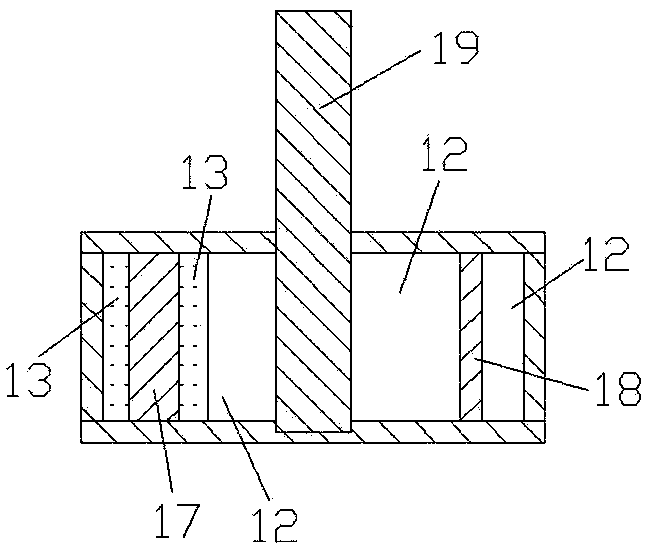
[0018] Such as Figure 1 to Figure 6 Shown, the present invention comprises compressor intake pipe 1, compressor 2, engine intake pipe 3, engine 4, first exhaust branch pipe 5, second exhaust branch pipe 6, exhaust pipe 7, turbine 8, turbine exhaust pipe 9. Connecting shaft 10, connecting pipe 11, volume cavity 12, fixed body 13, first through pipe 14, second through pipe 15, elastic member 16, partition 17, rotating body 18, first rotating shaft 19, connecting plate 20. The second rotating shaft 21, the first rotating plate 22, the third rotating shaft 23, the second rotating plate 24 and the chain 25, the air inlet and outlet of the compressor 2 are respectively connected with the air outlet of the compressor inlet pipe 1 and the engine inlet pipe 3 The intake port of the engine 4 is connected with the exhaust port of the engine intake pipe 3, and the air intake port of the first exhaust branch pipe 5 and the air intake port of the second exhaust branch pipe 6 are connected ...


PUM


Abstract

The invention discloses an exhaust manifold circulation area self-regulation type engine system in the technical field of mechanical design. The exhaust manifold circulation area self-regulation type engine system comprises a volume cavity, an elastic component, a rotating body, a division plate, a rotating shaft, a rotating plate and a chain, wherein the longitudinal section of the volume cavity is circular, the longitudinal sections of a fixed body and the rotating body are arc-shaped, an exhaust pipe is a uniform-section round pipe, a first through pipe and a second through pipe are both arranged in the fixed body, and the upper wall surface of the second through pipe and the division plate are connected together through the elastic component. When the pressure in an engine exhaust manifold is higher, the rotating body drives the rotating plate to rotate anticlockwise, the necking rate of the exhaust manifold is relatively large, and the pumping loss of an engine is less; when the pressure in the engine exhaust manifold is lower, the rotating body drives the rotating plate to rotate clockwise, the necking rate of the exhaust pipe is relatively small, the pulse energy can be utilized fully, and more available energy in front of a turbine exists. The exhaust manifold circulation area self-regulation type engine system is reasonable in design, simple in structure, and applicable to a turbocharger system with one turbine inlet and a side turbine.

Description

technical field [0001] The invention relates to a turbocharging system in the technical field of mechanical design, in particular to a self-adjusting exhaust branch pipe flow area engine system. Background technique [0002] With the development of society and the improvement of environmental protection requirements, the application of engine supercharging technology is becoming more and more extensive. Most of the engines with medium and high power adopt turbocharging technology to improve power and reduce fuel consumption. The two basic types of turbocharging systems are constant pressure supercharging system and pulse supercharging system. Constant pressure supercharging system, each cylinder shares an exhaust pipe with a large volume, the structure of the exhaust pipe system is relatively simple, the pressure in the exhaust pipe is basically kept constant, the pressure is only related to the load and speed of the engine, different cylinder numbers The supercharging syst...

Claims


Application Information

Patent Timeline
Patent Type & Authority Applications(China)
IPC IPC(8): F02B37/22
CPCY02T10/12
Inventor 王俊席
Owner SHANGHAI JIAO TONG UNIV
Why Eureka
Try Eureka