Optical fiber transmission system

A kind of optical fiber transmission and optical fiber technology, which is applied in the field of serial optical fiber transmission system, can solve the problems that cannot fully reflect the high bandwidth and long-distance transmission characteristics of optical fiber.

Inactive Publication Date: 2013-12-18
HONG FU JIN PRECISION IND (SHENZHEN) CO LTD +1
View PDF5 Cites 1 Cited by
  • Summary
  • Abstract
  • Description
  • Claims
  • Application Information

AI Technical Summary

Problems solved by technology

However, this cannot fully reflect the high bandwidth and long-distance transmission characteristics of optical fibers

Method used


Image

  • Optical fiber transmission system

Examples


Embodiment Construction

[0010] The optical fiber transmission system of the present invention will be further described in detail below in conjunction with the accompanying drawings and embodiments.

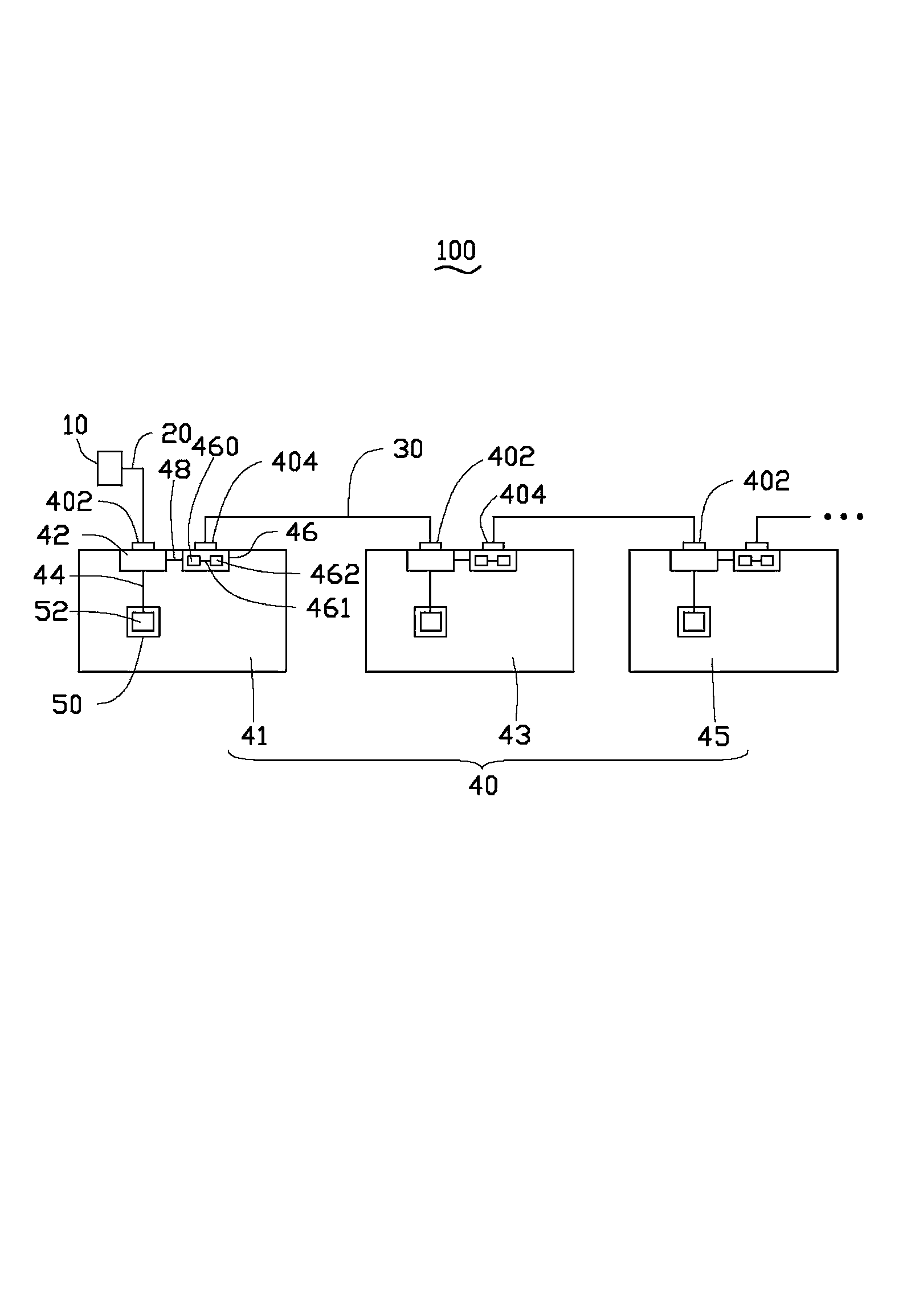
[0011] see figure 1 , an optical fiber transmission system 100 according to an embodiment of the present invention, which includes: an optical signal transmitting source 10 , a first optical fiber 20 , a plurality of second optical fibers 30 and a plurality of signal receiving devices 40 . In this embodiment, the first three signal receiving devices 40 of the plurality of signal receiving devices 40 are used to illustrate the present invention, that is, the first signal receiving device 41 , the second signal receiving device 43 and the third signal receiving device 45 . In this embodiment, the optical signal emitting source 10 is a laser diode, and in other embodiments, the optical signal emitting source 10 may also be other types of optical signal emitting sources.

[0012] The first signal receiving...


PUM


Abstract

The invention relates to an optical fiber transmission system comprising an optical signal transmitting source, a first optical fiber, a plurality of second optical fibers and a plurality of signal receiving device. Each signal receiving device comprises an input end, an output end and an optical receiving terminal. The input end of one of the signal receiving devices is connected with the optical signal transmitting source through the first optical fiber. Each second optical fiber is used for connecting the output end of one of two adjacent signal receiving devices and the input end of the other of the two adjacent signal receiving devices. Each signal receiving device further comprises a control module, a third optical fiber, a fourth optical fiber and a photoelectric conversion module, wherein the photoelectric conversion module is connected with the control module through the fourth optical fiber, the control module is connected with the input end and used for receiving optical signals from the first optical fiber or the second optical fibers, and the control module is connected with the optical receiving terminal through the third optical fiber.

Description

technical field [0001] The invention relates to an optical fiber transmission system, in particular to a serial connection type optical fiber transmission system. Background technique [0002] At present, the connection mode of the optical fiber transmission system is mainly radial. The radial optical fiber transmission system means that there is a conversion device between the light emitting source and the receiving terminal. The light emitting source transmits the optical signal to the conversion device through the optical fiber. The terminals are respectively connected to the conversion device through a plurality of wires. However, this cannot fully reflect the high bandwidth and long-distance transmission characteristics of the optical fiber. Contents of the invention [0003] In view of the above, it is necessary to provide an optical fiber transmission system that can fully reflect the high bandwidth and long-distance transmission characteristics of optical fibers....

Claims


Application Information

Patent Timeline
IPC IPC(8): H04B10/25
Inventor 许义忠
Owner HONG FU JIN PRECISION IND (SHENZHEN) CO LTD
Why Eureka
Try Eureka