Vacuum gripper device

A technology of vacuum clamps and clamps, which is applied in the direction of chucks, transportation and packaging, manipulators, etc., and can solve the problems of complex clamp connection, expansion of device scale, and decrease in vacuum efficiency.

Inactive Publication Date: 2013-12-18
KOREA PNEUMATIC SYST CO LTD
View PDF5 Cites 1 Cited by
  • Summary
  • Abstract
  • Description
  • Claims
  • Application Information

AI Technical Summary

Problems solved by technology

This means that in order to obtain the necessary vacuum or negative pressure, more energy and time are required
This does not ensure the economy of the system
[0006] Second, in the above system, since the vacuum pump is exposed outside
However, it is unreasonable to increase the scale of the device, increase the exhaust space to reduce the vacuum efficiency, and complicate the connection of clamps.

Method used


Image

  • Vacuum gripper device
  • Vacuum gripper device
  • Vacuum gripper device

Examples


Embodiment Construction

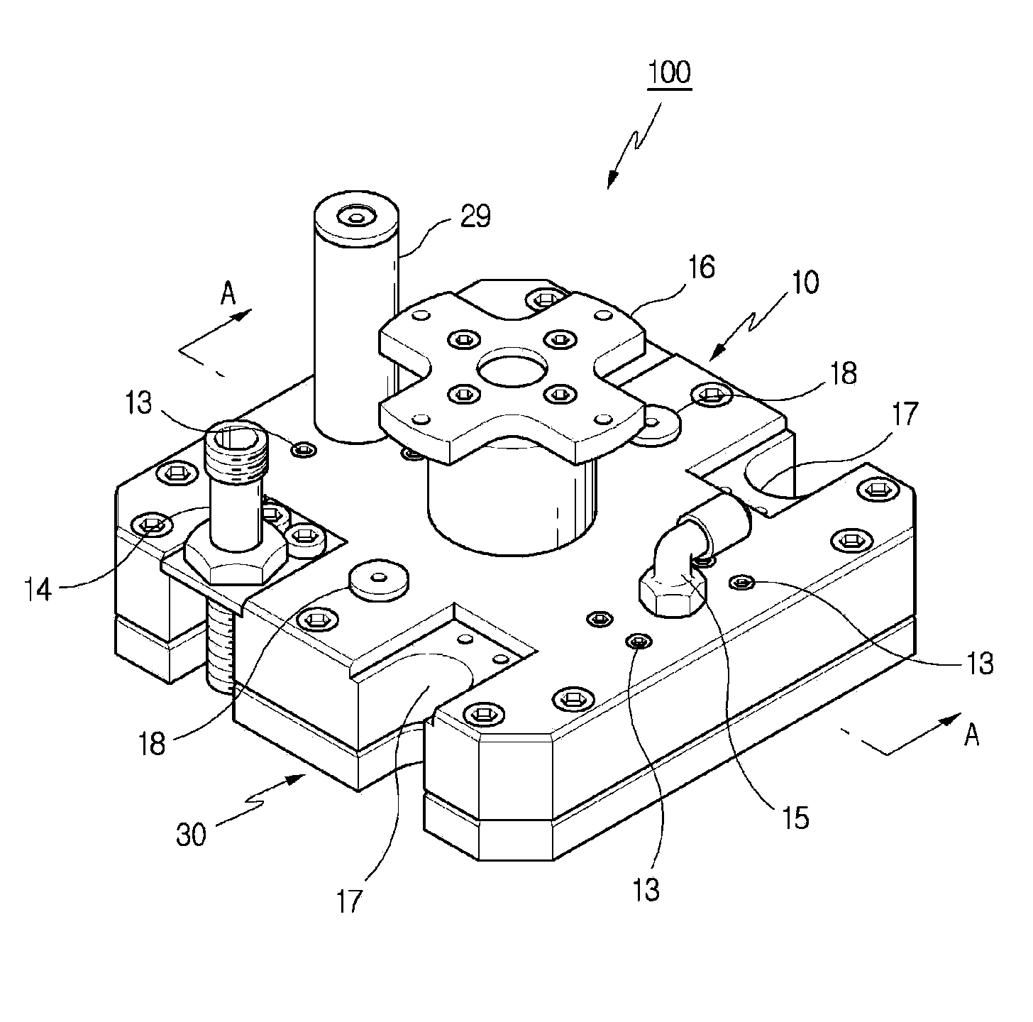
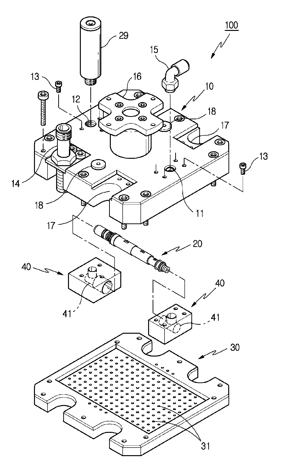
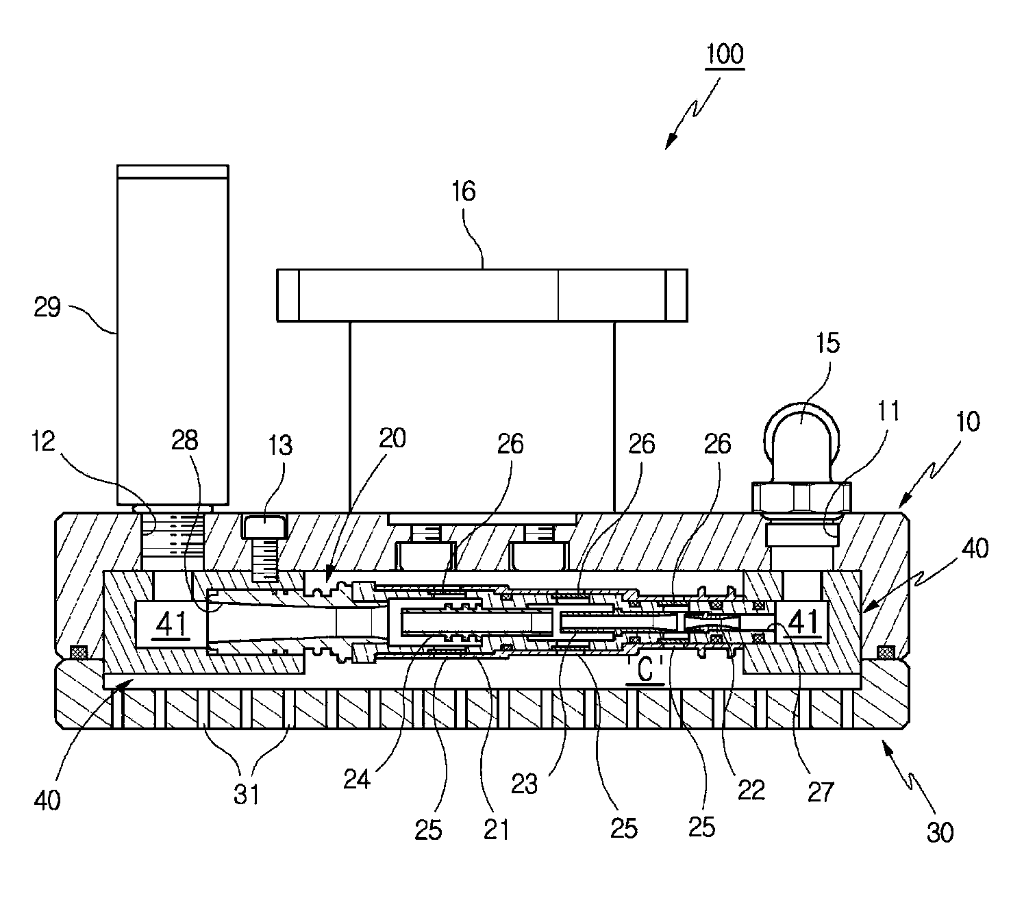
[0027] For the features and effects of the present invention that have been mentioned or have not been mentioned in the above description, we can further understand them through the following description of the embodiments with reference to the accompanying drawings. exist Figure 1 to Figure 4 Among them, symbol 100 represents a vacuum tong device according to the present invention.

[0028] refer to Figure 1 to Figure 3 It can be seen that the vacuum clamp device 100 of the present invention includes: a clamp body 10 combined with an adsorption plate 30 to form a negative pressure chamber C; a vacuum pump 20 built in the negative pressure chamber C of the above-mentioned body 10; in order to form a negative pressure chamber The lower part of C is the adsorption plate 30 combined with the above-mentioned body 10 .

[0029] The body 10 is a member combined with the lower adsorption plate 30 and has a negative pressure chamber C inside. The first hole 11 and the second hole ...


PUM


Abstract

The present invention relates to a vacuum gripper device mainly applied to a vacuum transfer system. The device of the present invention comprises a vacuum pump directly embedded in a negative pressure chamber of a gripper main body, and the main body is designed with a configuration for support and operation of the vacuum pump, such as a first hole and a second hole connected to an inlet and an outlet of the vacuum pump. The vacuum pump is desirably supported by a fixing block provided inside the negative pressure chamber. The present invention does not create any vacuum leak during the operation of the vacuum pump, and achieves vacuum quickly. In addition, the present invention is compactly and safely designed while including the vacuum pump.

Description

technical field [0001] The invention relates to a vacuum tong device, in particular to an adsorption tong device for holding objects in a vacuum transfer system. Background technique [0002] In general, a vacuum transfer system is composed of a vacuum pump, a hollow clamp, and a connecting line connecting the above two components. When the above two components are spaced a certain distance from each other, the connecting line is a hose or a pipeline. However, for example, when the above-mentioned vacuum pump is directly installed on the clamp, the above-mentioned connection line may also be an exhaust hole formed on the clamp. [0003] In the state where the object to be transferred is in close contact with the bottom surface of the above-mentioned gripper, high-speed compressed air is supplied to the inlet of one side of the vacuum pump, and then discharged through the outlet of the other side. During this process, the air inside the clamp is introduced into the vacuum p...

Claims


Application Information

Patent Timeline
Patent Type & Authority Applications(China)
IPC IPC(8): B65G47/91B25J15/06
CPCB65G47/911B25J15/0616B65G47/91B25J15/06
Inventor 赵镐英
Owner KOREA PNEUMATIC SYST CO LTD
Why Eureka
Try Eureka