Multistage self-locking and positioning device

A positioning device and self-locking technology, which is applied in the field of mechanical processing, can solve the problems that cannot meet the processing requirements of parts with different structures, and achieve the effects of reliable positioning, flexible operation and strong adaptability

Inactive Publication Date: 2013-12-25
SICHUAN HANGDA ELECTROMECHANICAL TECH DEV SERVICE CENT
View PDF0 Cites 6 Cited by
  • Summary
  • Abstract
  • Description
  • Claims
  • Application Information

AI Technical Summary

Problems solved by technology

[0002] With the continuous development of machining technology, the traditional three-jaw chuck positioning can no longer meet the processing

Method used


Image

  • Multistage self-locking and positioning device

Examples


Embodiment Construction

[0009] The present invention will be further described below in conjunction with the accompanying drawings.

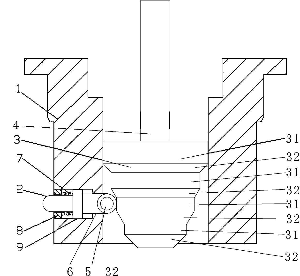
[0010] Such as figure 1 The multi-stage self-locking position device shown includes a positioning sleeve 1, a positioning pin 2, a multi-stage conical disk 3, a drive rod 4, a spring 7 and a screw sleeve 8, and is characterized in that it also includes a shaft 5 and a roller 6; The side wall of the positioning sleeve 1 is provided with a plurality of through holes, and a positioning pin 2 is arranged in the through hole, and a threaded sleeve 8 is fixedly installed on the outer end of the through hole, and a limit step 9 is arranged on the positioning pin 2, so that Said spring 7 is installed in the through hole, one end of which is pushed against the inner end face of screw sleeve 8, and the other end is pushed against the left end face of limit step 9; the lower end of said driving rod 4 extends into the center hole of positioning sleeve 1 and is fixedly connected wi...


PUM


Abstract

The invention discloses a multistage self-locking and positioning device, wherein multiple through holes are formed in the side wall of a positioning sleeve; positioning pins are arranged in the through holes; screw sleeves are fixedly installed on the outer ends of the through holes; limiting steps are arranged on the positioning pins; springs are installed in the through holes; one end of each spring is pressed against the inner end face of the corresponding screw sleeve; the other end of each spring is pressed against the left end face of the corresponding limiting step; the lower end of a drive rod stretches into a center hole in the positioning sleeve and is fixedly connected with the multistage self-locking and positioning device; the upper end of a screw rod stretches out of the positioning sleeve; a multistage cone dish (3) is provided with multiple cylindrical sections (31) and conical sections (32) at intervals, which are gradually shrunken or amplified from top to bottom or from bottom to top; the right ends of the positioning pins are provided with shafts; pulleys cooperating with the multiple cylindrical sections and conical sections are arranged on the shafts. By the adoption of the multistage self-locking and positioning device, the multistage cone dish is driven through the drive rod, so that the stretching length of each positioning pin is controlled; at the moment, various devices can be positioned quickly; moreover, when a roller moves to the cylindrical sections, the positioning pins implement automatic locking on the roller; therefore, the multistage self-locking and positioning device is flexible to operate and reliable in positioning.

Description

technical field [0001] The invention relates to the field of mechanical processing, in particular to a positioning and tightening device capable of realizing rapid positioning. Background technique [0002] With the continuous development of machining technology, the traditional three-jaw chuck positioning can no longer meet the processing needs of parts with different structures. The clamping and positioning method of parts has always been a design focus in the processing field. In the processing of a special part that needs to be processed through the hole position, it is the key to the processing technology to design a positioning device that can be processed through the hole as a positioning surface. Contents of the invention [0003] The technical problem to be solved by the present invention is to provide a positioning and tightening device with simple and flexible operation and reliable positioning. [0004] In order to solve the above-mentioned technical problems,...

Claims


Application Information

Patent Timeline
IPC IPC(8): B23Q3/00
Inventor 林敏
Owner SICHUAN HANGDA ELECTROMECHANICAL TECH DEV SERVICE CENT
Why Eureka
Try Eureka