Wellhead pipe righting device
A technology of pipe fittings and righting arms, which is applied in the field of righting wellhead pipe fittings, can solve the problems of troublesome disassembly, increased operation cost, complicated structure, etc., and achieves the effect that the righting process is simple and quick, and saves manpower and material resources.
- Summary
- Abstract
- Description
- Claims
- Application Information
AI Technical Summary
Problems solved by technology
Method used
Image
Examples
Embodiment 1
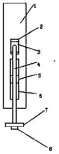
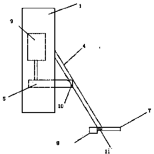
[0021] see figure 1 with figure 2 , the present invention is further described in detail: the outside of the mounting seat 1 is connected with a fixed shaft installation hole 2, the fixed shaft 3 is installed on the fixed shaft installation hole 2, the fixed shaft 3 fixes the upper end of the righting arm 4, and the lower end of the righting arm 4 The centering ring 7 and the balance weight 8 are connected to each other, and the centering ring 7 and the balance weight 8 are connected together by a balance shaft 11 and placed on both sides of the end of the centering arm 4. This structure ensures that the front and rear weights of the centering arm 4 are balanced, so that the centering ring 7 Always level.
[0022] An oil cylinder 9 is arranged inside the installation seat 1, and the bottom of the oil cylinder 9 is connected to one end of a support rod 5, and there is a groove at the bottom of the other end of the support rod 5. contact, the centralizing arm 4 can be fully e...
Embodiment 2
[0026] see figure 1 with figure 2 , the present invention is further described in detail: the outside of the mounting seat 1 is connected with a fixed shaft installation hole 2, the fixed shaft 3 is installed on the fixed shaft installation hole 2, the fixed shaft 3 fixes the upper end of the righting arm 4, and the lower end of the righting arm 4 The centering ring 7 and the balance weight 8 are connected to each other, and the centering ring 7 and the balance weight 8 are connected together by a balance shaft 11 and placed on both sides of the end of the centering arm 4. This structure ensures that the front and rear weights of the centering arm 4 are balanced, so that the centering ring 7 Always level.
[0027] Mounting seat 1 is provided with a cylinder 9 inside, the bottom of the cylinder 9 is connected to one end of a strut 5, and there is a groove at the bottom of the other end of the strut 5. contact, the centralizing arm 4 can be fully embedded in the groove.
[0...
Embodiment 3
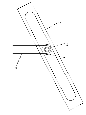
[0031] see figure 1 with image 3 , the present invention is further described in detail: the outside of the mounting seat 1 is connected with a fixed shaft installation hole 2, the fixed shaft 3 is installed on the fixed shaft installation hole 2, the fixed shaft 3 fixes the upper end of the righting arm 4, and the center of the righting arm 4 is along the The wall body is hollowed out, and the lower end of the centralizing arm 4 is connected with a centralizing ring 7 and a balance weight 8. The centralizing ring 7 and the balance weight 8 are connected together by a balance shaft 11 and placed on both sides of the end of the centralizing arm 4. This structure ensures The front and back weight balance of the righting arm 4 makes the righting ring 7 horizontal all the time.
[0032] A cylinder 9 is arranged inside the mounting seat 1, and the bottom of the cylinder 9 is connected to one end of the strut 5, and the other end of the strut 5 has a round hole. The connecting ro...
PUM
 Abstract
Description
Claims
Application Information
 - R&D Engineer
- R&D Manager
- IP Professional
- Industry Leading Data Capabilities
- Powerful AI technology
- Patent DNA Extraction
Browse by: Latest US Patents, China's latest patents, Technical Efficacy Thesaurus, Application Domain, Technology Topic, Popular Technical Reports.
© 2024 PatSnap. All rights reserved.Legal|Privacy policy|Modern Slavery Act Transparency Statement|Sitemap|About US| Contact US: help@patsnap.com


