
Gas injection position and nozzle number variable device

A technology of injection position and nozzle, which is applied in the direction of fuel injection device, oil supply device, charging system, etc., can solve the problems of invariable gas injection position and invariable number of nozzles, shorten the research and development cycle, and strengthen installation and disassembly Flexibility, the effect of saving development costs

Active Publication Date: 2015-11-11
JILIN UNIV
View PDF7 Cites 0 Cited by
  • Summary
  • Abstract
  • Description
  • Claims
  • Application Information

AI Technical Summary

Problems solved by technology

[0004] The technical problem to be solved by the present invention is to overcome the problems in the prior art that the gas injection position and the number of nozzles are not variable, and provide a device with variable gas injection position and nozzle number

Method used


Image

  • Gas injection position and nozzle number variable device
  • Gas injection position and nozzle number variable device
  • Gas injection position and nozzle number variable device

Examples


Embodiment Construction

[0036] The present invention is described in detail below in conjunction with accompanying drawing:

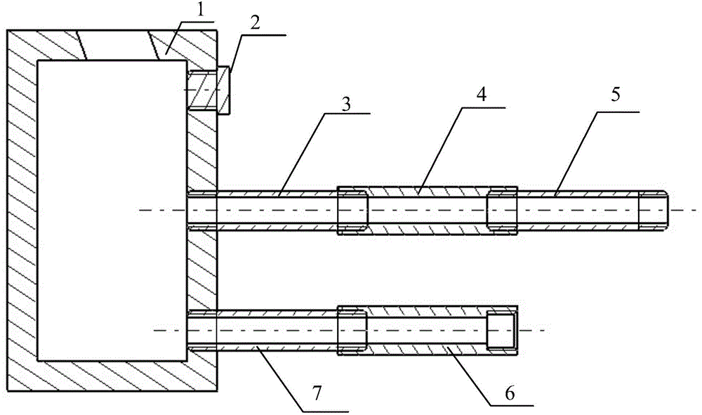
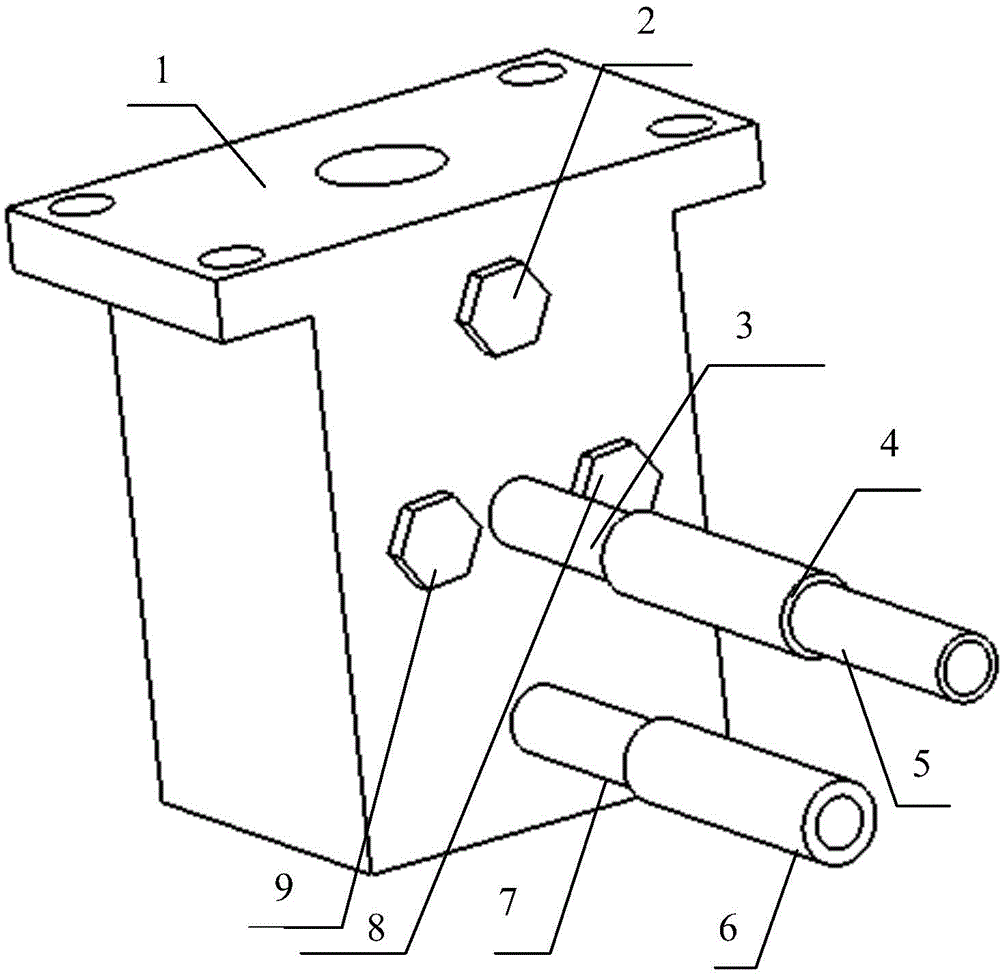
[0037] refer to figure 1 and figure 2 , The gas injection position and nozzle number variable device of the present invention is composed of a base 1, a nozzle assembly and a sealing assembly.

[0038] The nozzle assembly is installed in the gas injection hole on the base 1 for threaded connection, and the sealing assembly is installed in other gas injection holes on the base 1 for threaded connection.

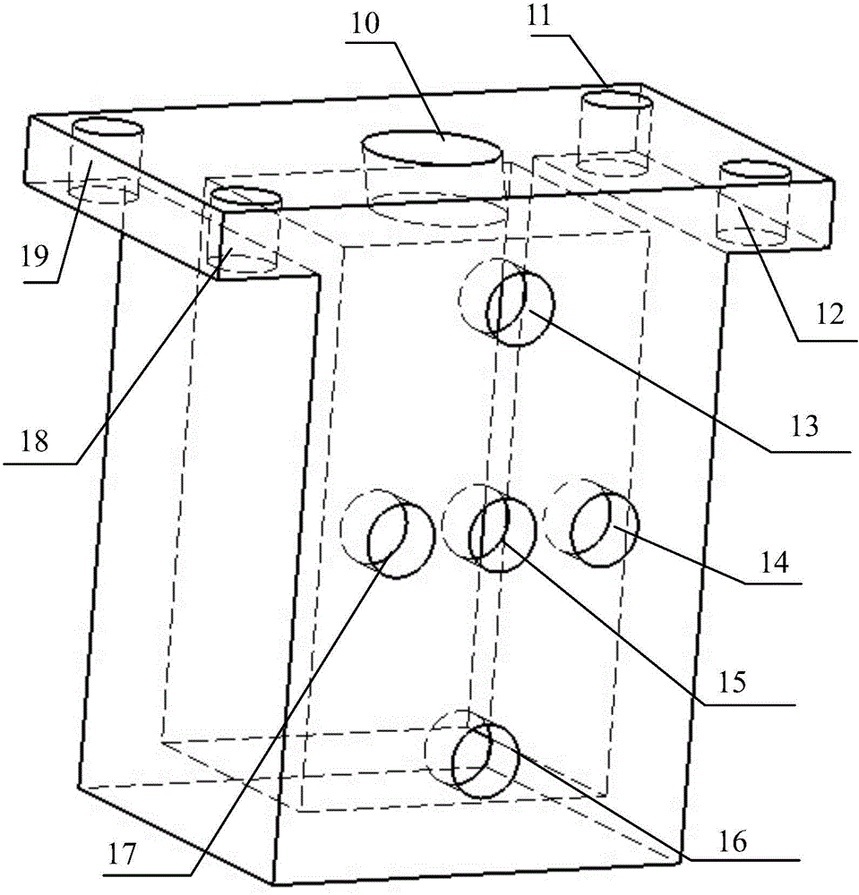
[0039] refer to image 3 , the base 1 is a cuboid structure with a cuboid cavity inside, a gas inlet port 10 is processed at the center of the top surface of the base 1, and mounting bolts are processed at the four corners of the top surface of the base 1 No. 1 fixed through hole 11, No. 2 fixed through hole 12, No. 3 fixed through hole 18 and No. 4 fixed through hole 19, wherein the shape of the gas inlet port 10 is the same as that of the gas connector (that is, a cylind...


PUM


Abstract

The invention discloses a device with a changeable gas injection direction and a changeable nozzle number, and aims to solve the problems that the gas injection direction and the nozzle number cannot be changed in the prior art. The device with the changeable gas injection direction and nozzle number is composed of a base (1), a nozzle subassembly and a sealing subassembly. The nozzle subassembly comprises a No. 1 nozzle, a No. 2, nozzle and a No. 3 nozzle with the same structure, wherein one end of one or two or three of the three nozzles is arranged in different gas orifices on the base (1) in a threaded connection manner. The sealing subassembly is composed of a No. 1 sealing bolt, a No. 2 sealing bolt, ellipsis, and a No. N-1 sealing bolt, wherein one or two ellipsis or N-1 of the No. 1 sealing bolt, No. 2 sealing bolt, ellipsis, and No. N-1 sealing bolt is / are arranged in different gas orifices on the base (1) in the threaded connection manner; N is the number of the gas orifices formed in the base (1), and N is greater than or equal to 1 and less than or equal to 9.

Description

technical field [0001] The invention relates to a gas injection device used in a gas fuel engine, more specifically, the invention relates to a device with variable gas injection position and number of nozzles. Background technique [0002] Gas fueled engines greatly reduce NO while reducing petroleum fuel consumption X It has made great contributions to improving the environmental pollution caused by vehicle exhaust and alleviating the dependence of countries around the world on petroleum fuels. The flow in the cylinder and the mixing state of gas and air have a great influence on the combustion of gaseous fuel. The gas intake method commonly used in gas fuel engines is multi-point injection in the intake port. The latest research results show that when the fuel enters the cylinder in the way of multi-point injection in the intake port, just like direct injection in the cylinder, the gas and air are not mixed uniformly. Therefore, the injection position of the gas in the...

Claims


Application Information

Patent Timeline
Patent Type & Authority Patents(China)
IPC IPC(8): F02M21/02F02M61/14F02M61/18
CPCY02T10/30
Inventor 王忠恕李伟峰刘忠长韩永强许允
Owner JILIN UNIV
Learn More