

Device with changeable gas injection direction and nozzle number
A technology of injection position and nozzle, which is applied in the direction of fuel injection device, oil supply device, charging system, etc., can solve the problems of invariable number of nozzles and invariable gas injection position, and achieve strong installation and disassembly flexibility, shorten The effect of research and development cycle and convenient processing
- Summary
- Abstract
- Description
- Claims
- Application Information
AI Technical Summary
Problems solved by technology
Method used
Image

Examples
Embodiment Construction
[0036] The present invention is described in detail below in conjunction with accompanying drawing:
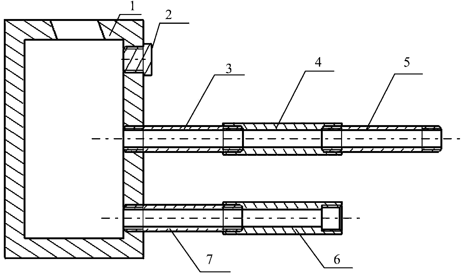
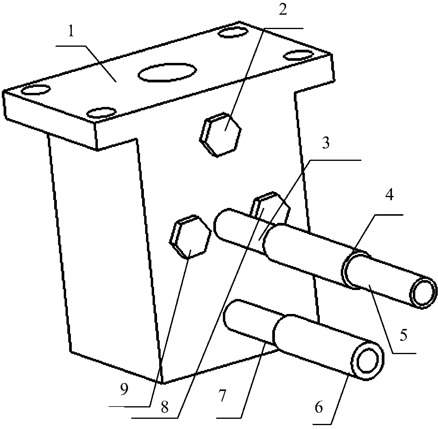
[0037] refer to figure 1 and figure 2 , The gas injection position and nozzle number variable device of the present invention is composed of a base 1, a nozzle assembly and a sealing assembly.
[0038] The nozzle assembly is installed in the gas injection hole on the base 1 for threaded connection, and the sealing assembly is installed in other gas injection holes on the base 1 for threaded connection.
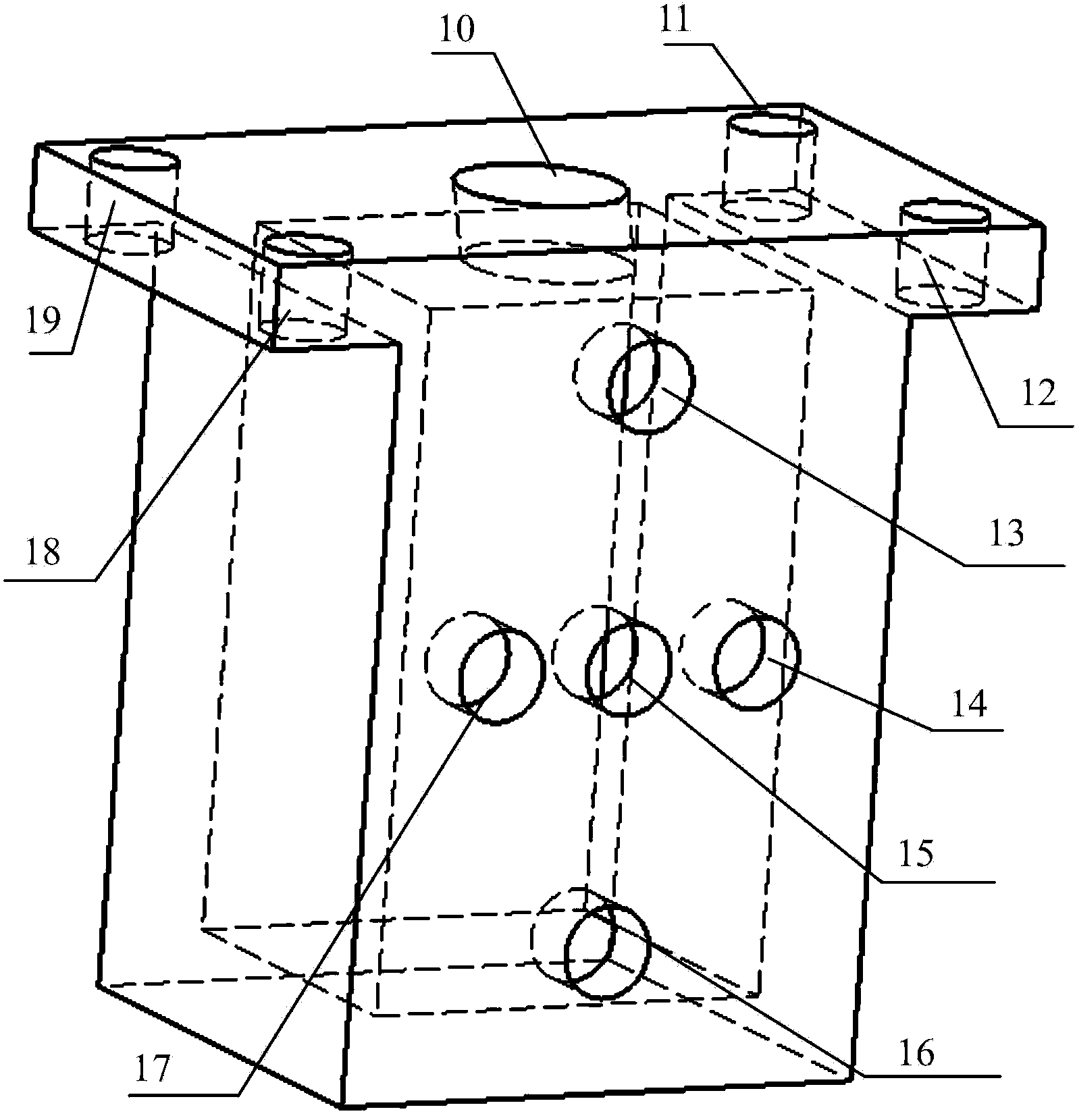
[0039] refer to image 3 , the base 1 is a cuboid structure with a cuboid cavity inside, a gas inlet port 10 is processed at the center of the top surface of the base 1, and mounting bolts are processed at the four corners of the top surface of the base 1 No. 1 fixed through hole 11, No. 2 fixed through hole 12, No. 3 fixed through hole 18 and No. 4 fixed through hole 19, wherein the shape of the gas inlet port 10 is the same as the shape of the gas connector (that is, a c...
PUM
 Abstract
Description
Claims
Application Information