
Phase change heat sink

A heat dissipation device and phase change technology, applied in the field of phase change heat dissipation devices, can solve the problems of staff's discomfort in operation and unusable heat dissipation fins, and achieve the effect of avoiding excessive temperature rise and high utilization efficiency

Inactive Publication Date: 2017-07-28
桐乡市桑美纺织有限公司
View PDF6 Cites 0 Cited by
  • Summary
  • Abstract
  • Description
  • Claims
  • Application Information

AI Technical Summary

Problems solved by technology

However, for some electronic devices with intermittent high-load operation, the high-load operation time is relatively short, and the standby or low-load operation time is relatively long. In a short period of time, it is transmitted to the air in the housing of the electronic device through the heat dissipation fins, resulting in the temperature of the housing being too high in a short period of time, which makes the staff feel uncomfortable when operating; while in standby or low-load operation, heat The components generate less heat without causing the temperature of the outer casing to rise, and the heat dissipation fins are not fully utilized at this time

Method used


Image

  • Phase change heat sink
  • Phase change heat sink

Examples


Embodiment Construction

[0012] The phase change heat dissipation device of the present invention will be further described in detail below in conjunction with the accompanying drawings.

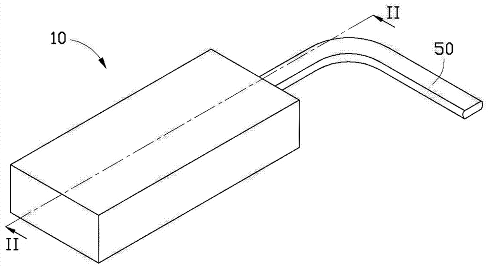
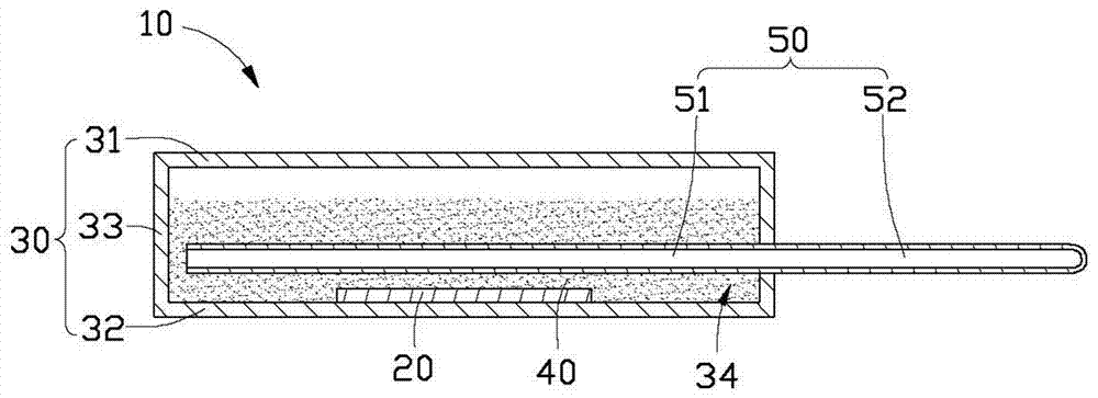
[0013] Please also see Figure 1 to Figure 2 , the phase change heat sink 10 of a preferred embodiment of the present invention is used to dissipate heat from the heating element 20 in the electronic device (not shown), which includes a housing 30 and a working medium arranged in the housing 30 40 and a heat pipe 50 connected to the shell 30.

[0014] Specifically, the housing 30 includes an upper cover 31 , a lower cover 32 opposite to the upper cover 31 , and a side wall 33 connecting the upper cover 31 and the lower cover 32 . Both the upper cover 31 and the lower cover 32 are flat and the size of the upper cover 31 is slightly larger than the size of the lower cover 32. The side wall 33 is formed by bending and extending upward from the periphery of the lower cover. The edge of the upper cover 31 is in contact ...


PUM


Abstract

A phase change heat dissipation device is used to carry out heat dissipation on a heating element. The device comprises a shell, a working medium arranged in the shell and a heat pipe connected with the shell. The heat pipe comprises an evaporation end and a condensation end. The working medium is a phase change insulation substance which is in a solid state at a normal temperature. The shell accommodates the heating element. The evaporation end of the heat pipe is extended into the shell and is contacted with the working medium. Compared to the prior art, by using the device of the invention, the shell of the phase change heat dissipation device accommodates the heating element and the working medium; the evaporation end of the heat pipe is extended into the shell and is contacted with the working medium; the working medium is the phase change insulation substance which is in the solid state at the normal temperature; during high load operation, the heat generated by the heating element is directly transferred to the working medium so that the working medium is liquefied and transient thermal storage is performed; when the heating element is in a standby state or carries out low-load operation, the working medium continuously carries out heat transmission and exchange and is conducted to an external portion through the heat pipe so that utilization efficiency is high.

Description

technical field [0001] The invention relates to a heat dissipation device, in particular to a phase change heat dissipation device which utilizes the principle of phase change to dissipate heat generated by electronic components. Background technique [0002] With the rapid development of electronic technology in recent years, the high-frequency and high-speed operation of electronic components and the density and miniaturization of integrated circuits make electronic components continue to generate heat during work. The heat generated during work is taken away to ensure the stable operation of electronic components. [0003] The traditional heat dissipation method is to install a metal heat sink above the heating electronic components. The heat sink has a base, the lower surface of the base is in contact with the electronic components, and a number of cooling fins are provided on the upper surface, and the base absorbs electrons. The heat generated by the components is tra...

Claims


Application Information

Patent Timeline
Patent Type & Authority Patents(China)
IPC IPC(8): H05K7/20
Inventor 陈荣安
Owner 桐乡市桑美纺织有限公司
Learn More